
RPM switch for 6th ports or VDI
Warning: Undefined array key "extension" in /var/www/html/nextgr/view-circuit.php on line 468
Deprecated: strtolower(): Passing null to parameter #1 ($string) of type string is deprecated in /var/www/html/nextgr/view-circuit.php on line 468

Two of these switches were constructed and installed in June during a VDI swap, and they have been functioning effectively since then. The cost of parts per switch is approximately $10 CAD. It is important to note that the installed switches were mounted away from heat sources to prevent potential adverse effects on the components. Additionally, LED indicators for power and the "switched on" state were incorporated, although these are not depicted in the circuit layout.
While reviewing the S5 FSM, it was observed that the auxiliary ports and VDI only function under load conditions. In this case, a GXL model equipped with auto-adjusting suspension features a switch on the accelerator pedal that sends a 12V signal to the AAS computer when the throttle exceeds half. To simulate the "under load" effect, the 12V power for the RPM switches was derived from this switch, ensuring that they operate only when full throttle is applied. This approach may be worth considering for those undertaking a VDI swap or converting auxiliary ports to electronic activation.
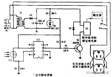
The adjustable RPM switch circuit typically consists of a microcontroller or timer IC that monitors the engine RPM, a potentiometer for setting the desired RPM threshold, and output control circuitry to activate the solenoids. The microcontroller receives input from the RPM sensor and compares it against the user-defined threshold set by the potentiometer. When the RPM exceeds the threshold, the microcontroller sends a signal to the output stage, which can drive the solenoid or other connected devices.
In addition to the core components, the circuit may include protective features such as flyback diodes across the solenoid coils to prevent voltage spikes when the solenoids are deactivated. Proper grounding and power supply decoupling are essential to ensure stable operation and minimize noise in the circuit. The use of LED indicators provides visual feedback, enhancing user experience and facilitating troubleshooting.
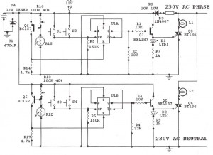
Overall, this adjustable RPM switch circuit represents a versatile solution for various automotive applications, particularly in enhancing the functionality of auxiliary systems. Its simple design, low cost, and adaptability make it an appealing option for automotive enthusiasts looking to implement electronic control in their vehicles.A circuit diagram for an adjustable rpm switch. It ’s something you can use to activate solenoids for auxiliary ports, VDI, shift light, or anything else you can think of. The circuit is adapted from a rev-limiter circuit for rotaries. In particular, I ’d like to thank Rob Weinstock from the fc3s. org list for his help tweaking it. I built and installed two of these switches in June when I did a VDI swap, and so far they ’ve been working fine. Parts cost per switch is only about $10 CAD! Note my installed photo, I ’ve mounted them away from heat, as I don ’t know how that might affect the components.
Also, not shown in the circuit layout, I added LED indicators for power, and the ‘switched on ’ state. One other note – I had been looking at the S5 FSM, and noted that the aux. ports and VDI only operate under load. I have a GXL, which came with auto-adjusting suspension. Part of that system is a switch on the accelerator pedal, which sends a 12V signal to the AAS computer above about half throttle.
To approximate the ‘under load ’ effect, I took the 12V power for the rpm switches from this switch, so they only operate when I ‘floor it ’. Just something you might want to try if you ’re doing the VDI swap or changing your aux. ports to electronic activation. 🔗 External reference
Related Circuits

The circuit utilizes six 12-volt lead-acid batteries to power the load. Three batteries are connected in series to generate 36 volts, while the other three are connected in parallel to maintain 12 volts. The total discharge current is 30...
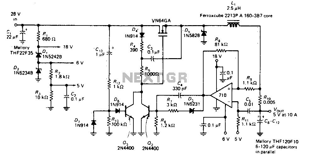
This circuit provides a regulated DC output with less than 100 mV of ripple for microprocessor applications. The required operating voltages are derived from a bleeder resistor network connected across the unregulated 28 V supply. The output of the...
Feedback in a public address amplifier should be avoided. The ideal solution is to adjust the positions of the microphone and speaker; however, this is not always feasible in many situations. A frequency shifter that alters the output frequency...
This circuit generates a constant current, constant voltage switched-mode power supply (SMPS). It is designed to efficiently charge a battery using a constant current, constant voltage approach. The circuit operates as a constant current, constant voltage SMPS, which is crucial...
Light Sensitive Staircase Switch with Triac. The operation of the third circuit is quite similar, except that it incorporates photo sensitivity. The circuit is illustrated in the schematic. When there is insufficient light... The light-sensitive staircase switch circuit utilizes a...
The flash beam can be utilized to power remote control devices for AC power applications. A key feature of this device is its memory function, which allows it to supply power continuously. Upon the second activation, the power will...