
RS 422 Compatible Indicator
The circuit design for the stepper motor controller includes a driver circuit that interfaces with the stepper motor, allowing for precise control of motor position and speed. The controller receives commands from a microcontroller, which processes the input signals and generates the appropriate control signals for the motor driver. The speed-controlled DC motor circuit is designed to regulate the speed of the motor based on feedback from a tachometer or other speed-sensing mechanism, ensuring that the propulsion system operates efficiently under varying load conditions.
The navigation system leverages a MEMS accelerometer to provide real-time data on the device's orientation and movement. The accelerometer outputs analog signals that are processed by the microcontroller to determine the device's position and trajectory. This information can be used to adjust the motor control signals, enhancing the overall responsiveness and accuracy of the system.
The communication protocol implemented for the indicator lamps utilizes a differential signaling method over the long-distance Category 5e cable, minimizing signal degradation and allowing for reliable data transmission. Each panel's unique address allows for selective control, ensuring that the correct commands are sent to the appropriate indicators without interference. This setup not only enhances the flexibility of the system but also provides scalability for future expansions, accommodating additional indicator panels as needed.
The choice of an ATmega16 microcontroller is strategic, as it provides sufficient processing power and I/O capabilities to manage multiple tasks simultaneously, including motor control, navigation processing, and communication with the indicator panels. The use of the internal RC oscillator simplifies the design by eliminating the need for external components, while still providing adequate timing accuracy for the application's requirements. Overall, the circuit design and firmware implementation exemplify efficient engineering practices, demonstrating the integration of various electronic components and systems to achieve a cohesive and functional application.design of the circuit and coding for the project`s stepper motor controller, the development of the circuit and coding for the speed-controlled DC motor for the project`s propulsion system, the circuit and coding for the system`s navigation system using a MEMS accelerometer circuit. This circuit is a bit of a departure from the rest of the content in this chapter, inasmuch as the appliance I describe here is not part of the E-2 project. The reason I have included this section is because the circuit and firmware illustrate several relevant and interesting points, including multidrop differential serial communications over relatively long distances and using the AVR`s internal RC oscillator instead of an external crystal. This application also provides a nice example of how the sorts of systems in this book can be used in real-world situations.
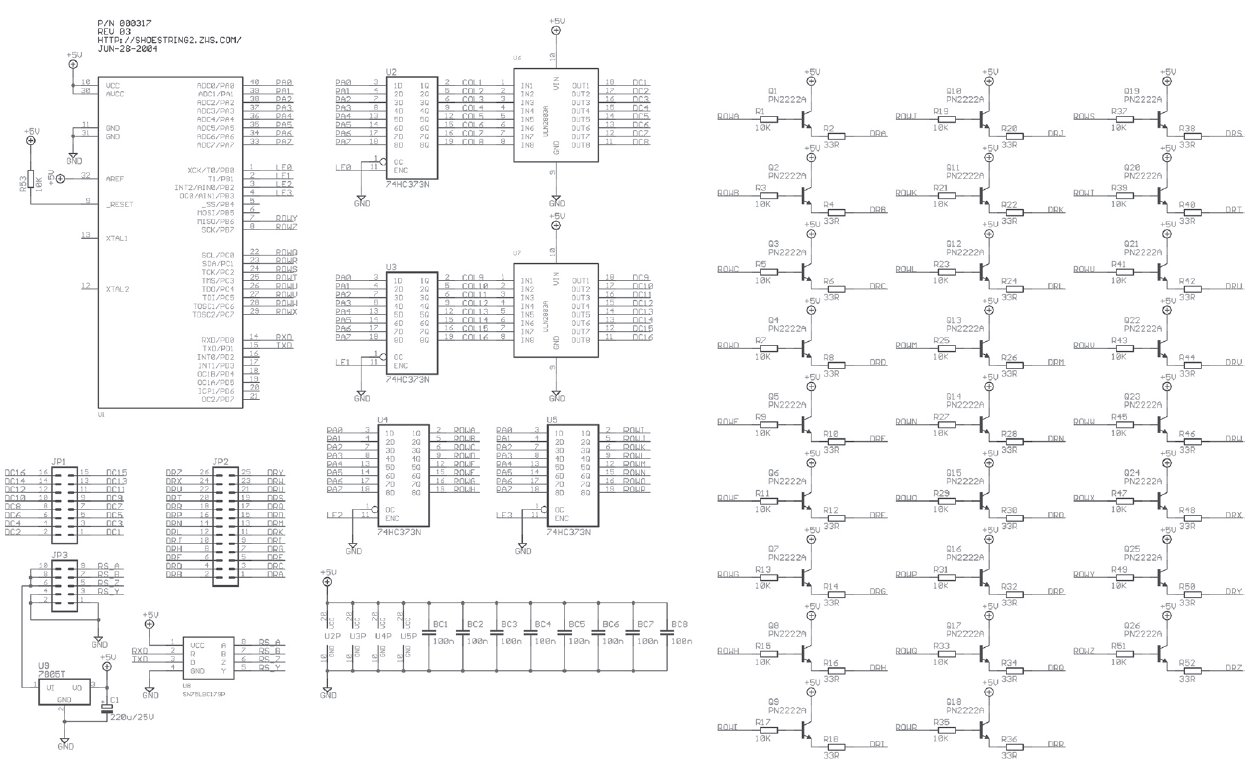
I developed this device for a shipping center application used in two of a company`s warehouses. The products shipped from these centers consist of standard and customized kits of individually-packaged parts. A number of conveyor belts run through the warehouse area, past the various bins of parts. At the "start" end of each conveyor belt is a large matrix of 416 pigeonholes arranged as 26 rows by 16 columns.
Before each shift, administrative staff stock these pigeonholes with pick-lists describing different standard subassemblies. Each pigeonhole has an indicator lamp (actually, an LED) over it. A central computer, connected to the company`s order processing system, controls all these indicator lamps over a piece of Category 5e cable that runs approximately 800 feet from the computer room to the warehouse floor; the indicator panels show workers along the conveyor belt which pick-lists to gather for an individual order as it progresses down the line.
As initially installed, all the panels were to repeat a single set of commands, however it was desired to leave the functionality open-ended so that in future, more panels could be added to the same bus, but show a different set of signals (to process multiple orders simultaneously on the same line). For this reason, each panel has an 8-bit address; commands coming down the wire have an address field indicating the intended recipient.
It`s legal for multiple indicators to have the same address if you want them to repeat duplicate data. The actual LEDs are omitted from this schematic for clarity`s sake; they are wired in a simple matrix with the cathodes connected to the ULN2803s driving the column lines, and the anodes connected to the row lines.
I chose an ATmega16 part for this design purely for the large I/O and memory budget; although it would be possible to implement the project in a much smaller part, it was simply convenient and quick to pick the mega16. You`ll observe that this project uses the AVR`s on-chip clock generator rather than relying on an external crystal.
Note that the internal RC oscillator in the AVR parts is factory-calibrated with a device-specific "fudge factor. " This fudge factor is different for each supported oscillator speed. The specific calibration constants for each frequency are stored in a nonuser-accessible (probably OTP) area of the micro, and can be read out with the chip signature.
They cannot be read directly by code running on the target device; you can only read them out with a device programmer like the STK500. You`ll notice that the code I provide is set up for 1 MHz operation, but that I have also included commented-out initialization code for 8 MHz operation.
If you want to run the project at 8 MHz, you need to do slightly more than just uncommen 🔗 External reference
Related Circuits
The output voltage can be increased easily by placing a resistor in parallel with Ra until it reaches precisely 5.0 V. Switches S1 and S2 are preferably SPDT types with a center position, but three-way rotary switches can also...
When the water level is below the steel rods, there is no contact between the metal can and the rods, which are supported by a small insulated wooden board. The circuit built around IC1 draws no current, resulting in...

This is a design of the circuit diagram for an RS422 interface. Connector K1 is connected to the serial port of the PC, and power for the PC side of the circuit is obtained from the signal lines DTR...
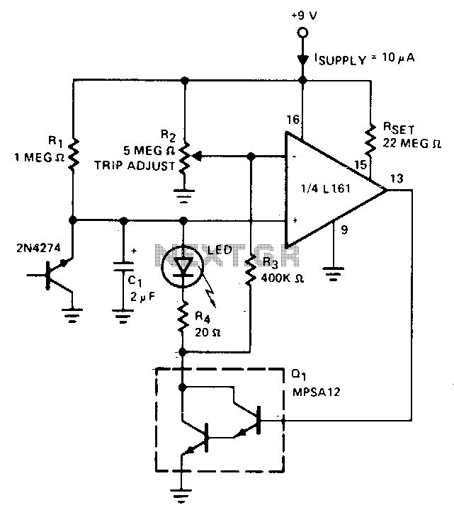
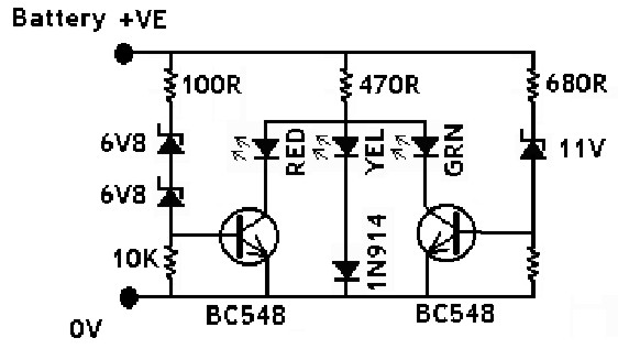
The indicator flashes an LED when the battery voltage drops below a certain threshold. The 2N4274 emitter-base junction serves as a zener diode, establishing approximately 6V on the L161's positive input. As the battery voltage decreases, the output of...
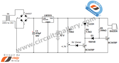
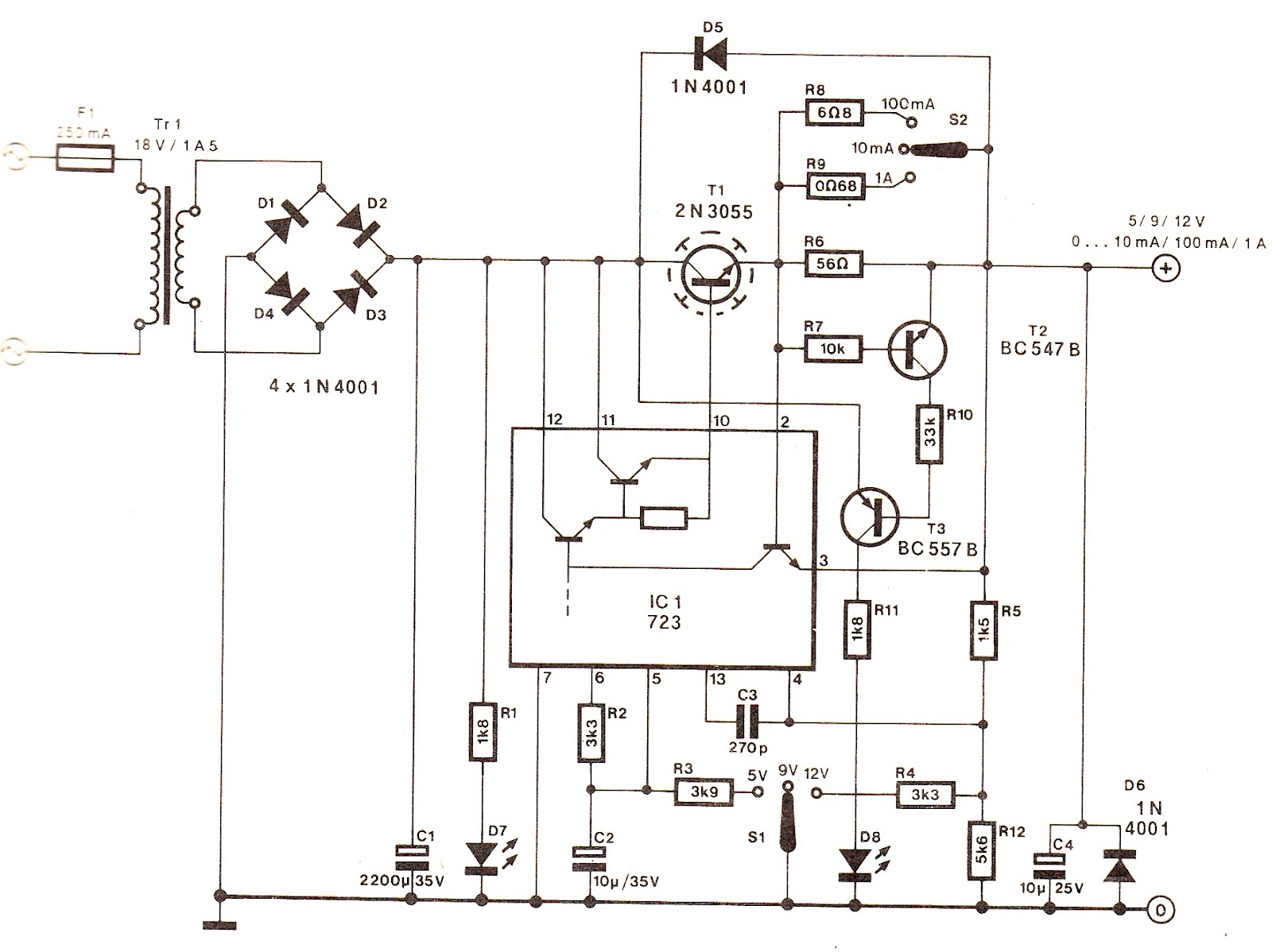
This is a straightforward 12V rechargeable smart battery charger circuit. It can be utilized as a charger for car batteries, inverter batteries, emergency light batteries, and more. An automatic indicator alarm circuit accompanies this battery charger schematic. The primary...
The IN914 (small glass diode) and the zener diodes have bands on their bodies that must be oriented according to the diagram provided. The bands are located at the cathode end of the diodes. A magnifying glass can assist...