
RS232 Dev Board
The RS232 project described is a practical implementation aimed at simplifying the interfacing of microcontrollers with PC serial ports. The circuit operates within the constraints of standard RS232 communication while leveraging the lower voltage levels accepted by modern serial ports. The use of a voltage regulator or zener diode ensures that the microcontroller receives a stable power supply, critical for reliable operation.
The inclusion of 1N4148 diodes is a protective measure, ensuring that any potentially harmful negative voltages do not damage the microcontroller or other components. The transistor switches play a crucial role in adapting the signal levels between the microcontroller and the serial port, effectively translating the binary signals for proper communication.
Furthermore, the design's adaptability to different microcontrollers highlights its versatility, as many microcontrollers share similar communication protocols and voltage requirements. The necessity of grounding the breadboard adds an extra layer of safety and stability, ensuring that the circuit operates without interference from stray voltages or noise.
In summary, this RS232 project exemplifies a straightforward yet effective approach to power and communication for embedded systems, showcasing essential electronic components and design considerations that enhance functionality and reliability.A simple RS232 example project that takes all the power it needs from the serial port. Use it to power your microcontroller and communicate between serial port and microcontroller. Takes advantage of the fact that pc serial ports will accept 0-5V rather than the RS232 standard of around negative 10V to positive 10V. Very convenient - no external p ower required! Note that you may use either a 5. 1V zener or a 5V regulator. In the circuit above, the two 1N4148 diodes prevent any negative voltage getting into the rest of the circuit if either DTR or RTS would happen to go negative. The two transistors function as transistor switches. The transistors also act as inverters. We need to invert things since the pc serial port uses positive voltage to represent binary 0 (RS232 SPACE) and negative voltage (or lucky for us 0 voltage) for binary 1 (RS232 MARK).
Of course the voltage regulator regulates the voltage with some decoupling capacitors. A zener diode can also be used to regulate the voltage. In my schematic, you can see that I developed this for my PIC projects, but other microcontrollers will probably have similar serial communications methods and similar supply voltage requirements. One thing I needed to do to use this with my solderless breadboard was to connect the metal on the bottom of the breadboard to ground.
You may need a similar sort of grounded shielding near your circuitry if you use this. 🔗 External reference
Related Circuits
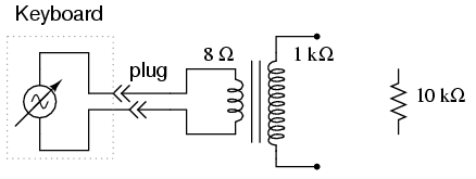
An electronic musical keyboard serves as a source of variable-frequency AC voltage signals. It is not necessary to purchase an expensive keyboard; a model with at least a few dozen voice selections (such as piano, flute, harp, etc.) is...
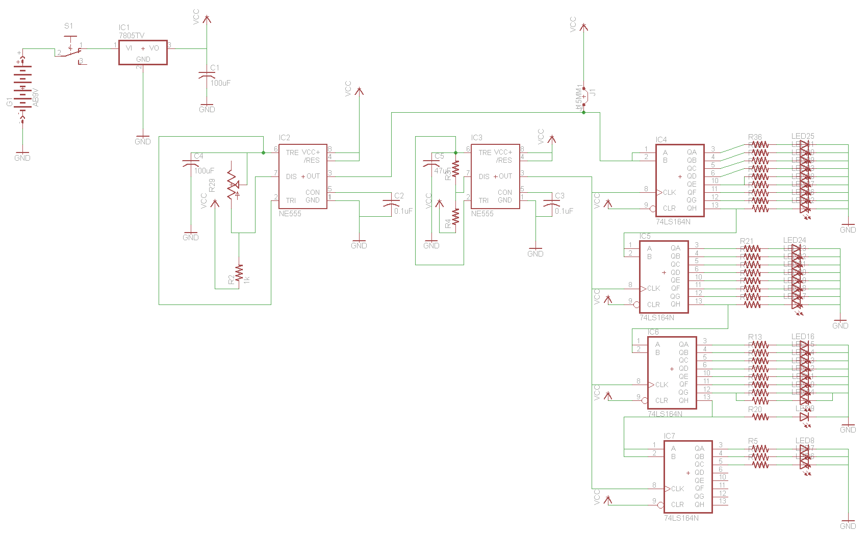
For the two-layer board schematic, six core integrated circuits (ICs) will be utilized: four 74LS164 shift registers and two 555 timers. The schematic will be constructed using the Eagle Layout Editor, as all required components are available in its...
Development board for 18-pin PIC microcontrollers featuring a power supply circuit, crystal oscillator circuit, RS232 port, ICSP/ICD port, 4 relay outputs, and 4 optocoupler isolated inputs. This development board is designed to facilitate the prototyping and testing of applications utilizing 18-pin...
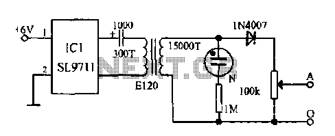
The electronic frostbite treatment instrument ASIC SL9711 consists of an oscillation circuit, a power amplifier, and a controller. It generates a sine wave at frequencies of 100 Hz and 3 Hz, followed by a step-up transformer with potentiometer adjustment...
8051SBC USB and GLCD Expansion Board, electronic circuit schematic wiring diagram for the 8051SBC USB and GLCD Expansion Board. The 8051SBC USB and GLCD Expansion Board is designed to enhance the functionality of the 8051 microcontroller system by providing additional...
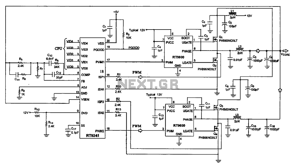
A typical computer motherboard CPU power supply circuit is primarily composed of the main power supply management chip RT9241 and additional components from the power management chip RT9600. The voltage command signal from the CPU is input into the...