
RS232 to RS485 Converter
The RS232 to RS485 converter is designed to facilitate communication between devices using different serial communication standards. The RS232 interface, commonly found in PCs, operates on a single-ended signaling method, while RS485 employs differential signaling, which allows for longer distances and increased noise immunity.
The circuit incorporates a DE9 connector for the RS232 interface, providing compatibility with standard PC serial ports. The TxD (transmit data) and RxD (receive data) signals from the RS232 are translated to RS485 signals, ensuring that data can be sent and received effectively across the two standards.
Direction of data transmission is managed by the RTS (Request to Send) line from the PC, which controls the direction of the RS485 communication. This allows for half-duplex communication, where the device can either send or receive data at any given time, but not simultaneously.
To ensure compatibility with various software applications, a handshake loop is implemented in the PC connection. This feature guarantees that the converter can operate seamlessly with different types of software, making it versatile for various applications.
The RS485 signals are output through a 6-way modular jack, facilitating easy connectivity to other RS485 devices. Additionally, indicator LEDs are included in the design to provide visual feedback regarding communications traffic, allowing users to monitor the status of data transmission effectively.
Power for the converter is supplied through an external unregulated 9V plug pack, which powers the circuit components.
Several additional features enhance the functionality of the converter. A jumper-selectable RS485 termination resistor is included to minimize signal reflections on long cable runs, which is crucial for maintaining signal integrity. Furthermore, pull-up and pull-down resistors are implemented on the RS485 lines to establish a defined idle condition, ensuring that the lines are not left floating when no data is being transmitted.
Overall, this RS232 to RS485 converter project serves as an educational example of circuit design principles while providing a practical solution for interfacing different serial communication standards.The project we have chosen as our example is an RS232 to RS485 converter. This is a often needed device which can demonstrate a lot of principles of circuit design, and hopefully the finished project will be useful to some people, just as it stands. Without meaning to confuse the issue, we also have available a second, more up-to-date 232-to-485 converter.
This project demonstrates how we produce an electronic project using one particular PCB CAD package. Our business is about producing finished custom electronics, and the PCB design process is an important part of that. This page might be of interest to new designers wanting to learn principles, or to potential clients wanting to understand our processes more thoroughly.
DE9 RS232 connector compatible with PC TxD and RxD translated from RS232 to RS485 Direction of transmission controlled by PC RTS line Handshake loop the PC connection so it works with all software RS485 signals output on 6 way modular jack Indicator LED(s) to show communications traffic Power supplied by external unregulated 9v plugpack ... and a few extra features, not essential, but desirable RS485 Termination resistor, jumper selectable Pullup/Pulldown resistors on RS485 to establish line-idle condition
🔗 External reference
Related Circuits
The VGA-to-Scope converter schematic has been simplified by removing op-amp buffers and inverters. A 1 Megohm potentiometer can be used instead of a continuous current supply to charge the capacitor from a 5V source. Proper placement of the potentiometer...
There are instances where a 5-V supply voltage is available, but certain components within the circuit require a lower voltage supply. In such cases, a voltage regulator from the Texas Instruments TPS62000 family is an excellent solution, particularly when...
In many situations, there is a need for a 220VAC voltage supply in areas where it is not readily available to power various small appliances. Figure 1 illustrates a voltage converter circuit that converts 12VDC to 220VAC, with an...
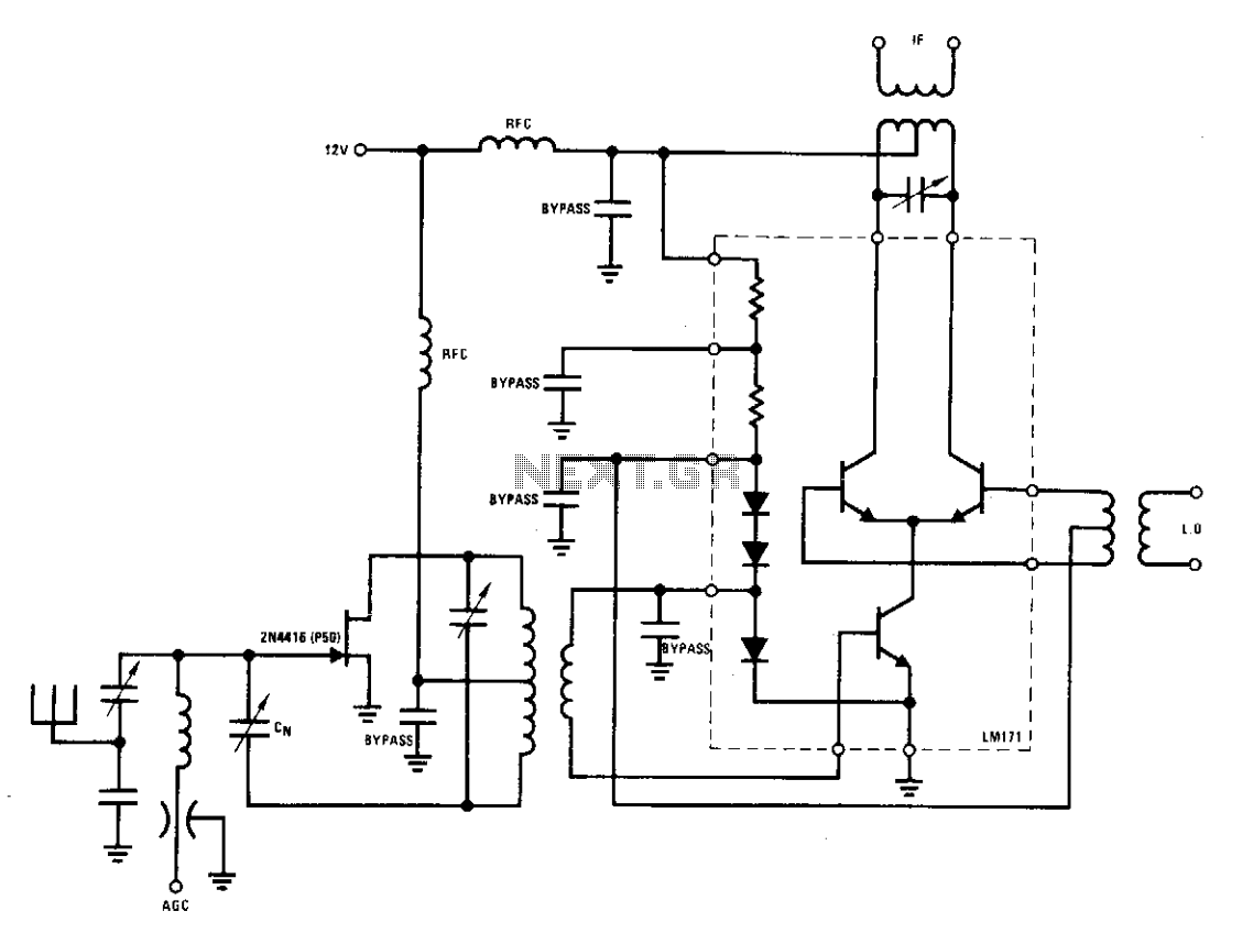
The 2N4416 JFET offers noise figures below 3 dB and a power gain exceeding 20 dB. Its exceptional low crossmodulation and low intermodulation distortion make it an ideal choice for an input stage. The output connects to an LM171,...
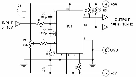
A voltage-to-frequency converter with a control range of 1:1000 can be constructed using the IC TSC9402. The specified component values in the circuit yield a conversion factor of 1 kHz per 1 V. Input voltages ranging from 10 mV...
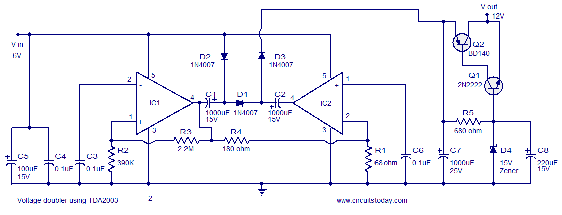
A reliable voltage converter circuit that operates between 6 to 12 volts, utilizing the audio amplifier IC TDA 2003. This voltage doubler circuit can be assembled on a Vero board. The voltage converter circuit designed with the TDA 2003 audio...
Warning: include(partials/cookie-banner.php): Failed to open stream: Permission denied in /var/www/html/nextgr/view-circuit.php on line 713
Warning: include(): Failed opening 'partials/cookie-banner.php' for inclusion (include_path='.:/usr/share/php') in /var/www/html/nextgr/view-circuit.php on line 713