
voltage frequency converter

A voltage-to-frequency converter utilizing the TSC9402 IC is designed to achieve a significant control range of 1:1000, facilitating the conversion of varying input voltages into corresponding frequency outputs. The circuit operates effectively within the input voltage range of 10 mV to 10 V, translating these values into frequency outputs that span from 10 Hz to 10 kHz. This conversion is primarily determined by the component values selected in the circuit, ensuring a conversion factor of 1 kHz for every volt applied.
The circuit's configuration includes a potentiometer, P1, which allows for fine-tuning of the conversion characteristics to meet specific application requirements. The two output signals generated by the circuit cater to different needs: pin 8 outputs a sharp pulse representing the main output frequency, while pin 10 provides a clean square wave at half the frequency of the signal from pin 8. This dual output capability enhances the circuit's versatility in various applications.
Calibration of the circuit is critical for accurate operation. This is achieved by employing a precise frequency counter to adjust the potentiometer P1, ensuring that an input voltage of 10 mV corresponds to a 10 Hz output frequency. This calibration step is essential for applications where precise frequency outputs are required, such as in telemetry systems.
In telemetry applications, the voltage-to-frequency conversion is particularly beneficial for transmitting voltage measurements over distances. The converted frequency can be transmitted through coaxial cables or utilized in wireless telemetry systems. The output from the converter can modulate a carrier signal in a transmitter, allowing for radio frequency transmission of the measured data. However, it is important to note that the maximum output frequency is limited to 10 kHz, which corresponds to a maximum input voltage of 10 V.
For remote measurements using coaxial cables, a diagram illustrates the configuration, emphasizing that while effective, the technique is limited to short distances, typically a few meters. To overcome this limitation, a signal amplifier can be integrated to extend the transmission range. Furthermore, the circuit can be adapted for radio transmission, where the modulated signal can be transmitted over longer distances. Utilizing satellite transponders for signal relaying can facilitate global telemetry capabilities, enabling the collection and transmission of data from remote locations worldwide.A voltage to frequency converter with a control range of 1:1000 can be easily constructed by using the IC TSC9402. The given component values in the circuit produces a conversion factor of 1kHz/1V. The input voltages from 10 mV up to 10 V are converted to frequencies 10 Hz up to 10 kHz. This conversion can be changed if desired through the potenti ometer P1. The circuit has two outputs: a sharp pulse comes out from pin 8 with the main output frequency. A clean squarewave comes out of pin 10 but its frequency is half of the output frequency at pin 8. Calibration: use an accurate frequency counter and adjust P1 so that an input level of 10 mV will produce a signal of 10 Hz at the output. One area of application for this circuit is the telemetry. In this case, telemetry of voltage values. By converting the voltage value to a frequency, the value can be transmitted either via a coaxial cable or radio.
Wireless telemetry method using radio, can be realized by using the output of this circuit to modulate the carrier signal of a transmitter. It is not possible to use directly the output frequency of this circuit since it produces only a maximum of 10 kHz (equivalent to a measured voltage of 10 volts at its input).
The following diagram shows how to use the circuit for remote measurements using a coaxial cable. The technique is limited to several meters though. The distance can be increased by using a signal amplifier. The diagram on the right shows the circuit modulating a transmitter to transport the measured value via radio signals. This technique allows remote telemetry over very long distances. If the signal is repeated via a satellite transponder, the telemetry can be done worldwide. 🔗 External reference
Related Circuits

The LTC3113 fixed frequency buck-boost DC-DC converter can be utilized to design various power supply circuits that operate with input voltages that are above, below, or equal to the output voltage. The topology integrated into the IC ensures low...
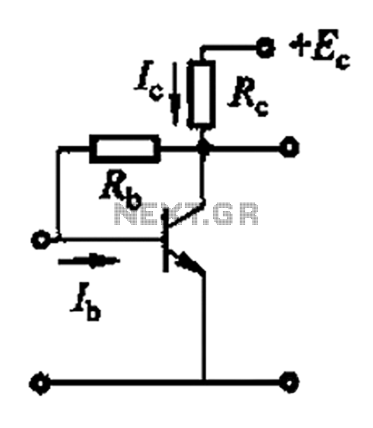
Basic reference bias circuit using a transistor with negative voltage feedback. The basic reference bias circuit utilizing a transistor with negative voltage feedback is designed to provide a stable output voltage or current that is largely independent of variations in...
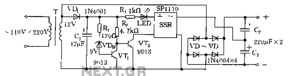
The circuit is automatically converted to a low-voltage configuration. A 220V AC supply is stepped down by transformer T. After this, the breakdown voltage of diode VDw causes transistors VT1 and VT2 to turn off, resulting in the solid-state...
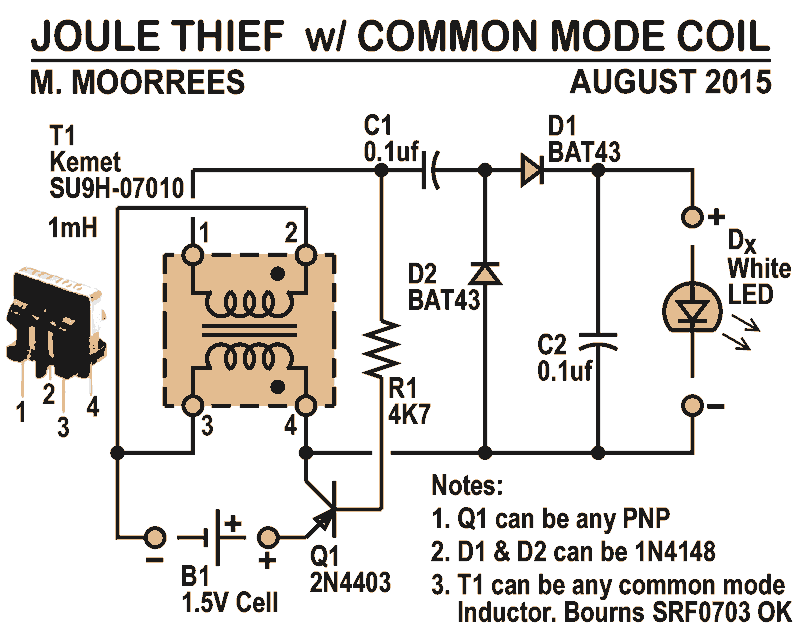
Like all joule thieves, this circuit boosts the voltage from a single 1.5V dry cell battery high enough to illuminate ultrabright GaN blue, green, or white LEDs. Instead of requiring a custom coil, it utilizes an off-the-shelf standard Kemet...
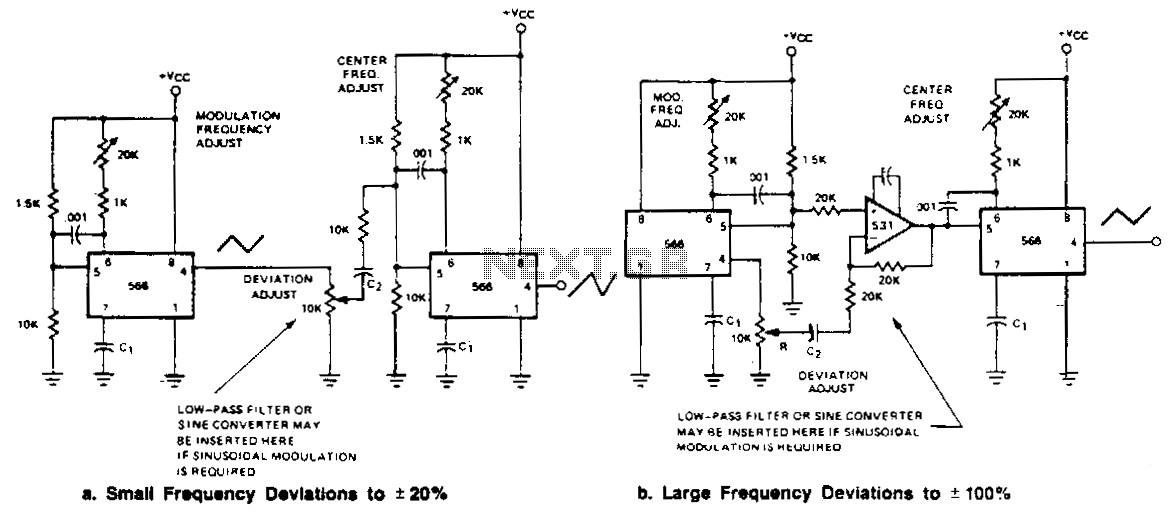
Two FM generators are presented for low frequency applications with a center frequency of less than 0.5 MHz. Each generator utilizes a 566 function generator as a modulation generator and a second 566 as the carrier generator. Capacitor C1...
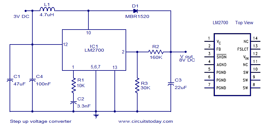
A simple DC to DC step-up voltage converter circuit schematic using the LM2700, which is a step-up switching converter. The LM2700 is a versatile step-up switching converter designed to efficiently convert a lower input voltage to a higher output voltage....