
rtc circuit

The miniature real-time controller circuit is designed to efficiently manage multiple household appliances through a compact and programmable system. The core component, the 89C2051 microcontroller, serves as the brain of the operation, executing the timer6.hex program to maintain time and control the outputs. The use of a low-cost crystal oscillator ensures that the device remains affordable while providing accurate timing functionality.
The six-channel output capability allows users to control various appliances independently, with the ability to program schedules directly from a PC. This feature enhances user convenience, enabling automated operation of devices such as lights and air conditioning units based on user-defined time intervals. The 20 mA sinking current capability of each output channel is sufficient for driving opto-triacs and solid-state relays, which are essential for managing higher power loads safely and efficiently.
The design incorporates a robust backup power system using 1N914 diodes, ensuring that the microcontroller remains operational even in the event of power fluctuations. The absence of brownout protection highlights an area for potential improvement, particularly for applications where battery power is a primary source. The ability to reset the device by removing and reinserting the battery provides a simple workaround for operational issues.
The RS232 communication interface allows for easy programming and interaction with the device, with flexibility to use various level converters. The option to customize the year readout for specific regional requirements, such as the Buddhist Era in Thailand, demonstrates the adaptability of the system to meet local needs.
Overall, the miniature real-time controller circuit exemplifies a well-thought-out design that balances functionality, cost, and user-friendly features, making it an effective solution for home automation applications. The integration of a programmable scheduler, manual control options, and the ability to handle multiple devices positions this controller as a valuable tool for modern household management.A Miniature Real-time Controller controls night light, A/C, household appliances with programmable scheduler. Modified source code and hex file for year 2002 readout. This is my long history the device that controls my home`s night light, air-conditioner, etc. The device is a Miniature Real-time Controller. The circuit uses only three chips, a 89C2051, DS275(or MAX232), and 74LS07 open collector driver. The scheduler for time on/off of 6-channel output can be made by downloading from PC and saved into onchip RAM. Each output provides a 20mA sinking suitable for driving a homemade opto-triac or big solid-state relay for heavy load.
A circuit diagram of the Miniature Real-time Controller is shown in Figure 1. A 89C2051 with a low-cost X-tal 3. 579MHz runs timer6. hex. The 6-channel output is P1. 2 to P1. 7 driving with sink current. A 74LS07 open collector provides approx. max 20mA @12V suitable for driving a homemade opto-triac shown in Figure 2. Two signal diodes, 1N914, provide simple backing up supply for the 89C2051. Since RST uses simple RC circuit, there is no brownout protection and reset switch thus when the controller operated with battery for long time, the chip may knock. Simply take the battery out and put them again. The RS232 level converter, instead of DS275, any converter may use, say MAX232, or simple circuit using two transistors.
An opto-triac with zero-crossing can be made easily. I have used an MOC3041 to drive 5A 240V triac. A night light used in my home mostly be an incandescent lamp, the circuit below works fine. For such heavy load as air-conditioner, I used a solid-state relay, one from CRYDOM D2410, say. Example of scheduler air. pgm was written as a text file. Downloading to the controller may simply do via communication program, Xtalk or any others program but sending each character should matched the receiving speed of the controller. For Xtalk, the speed may reduced by changing CWAIT command( there`s no XON/XOFF flow control). I got a mail asking for changing year readout. The readout shown in Figure 4 is for Thailand, we use Buddhist Era. So I modified the byte 25 to 20. This byte is fixed to 20, next 100 years you have to change it again to 21, say. But I thought may be no need anymore. The new version of miniature real-time controller is developed with c source code and use 8051SBC as a terminal for time setting.
Time scheduler is fixed. To modify it, edit the array, PGM[] and recompile the source code. Figure 5 shows the connection using RS232 cross cable between RTC and 8051SBC. The onboard two buttons are used for HOUR and MIN adjusting. Main program is timer0 interrupt driven. The timer0 is set to 16-bit timer mode with 1/10s interrupt rate. Every 0. 1s the time functions is entered updating the clock. In time function, the program prints current time every one second and scans the preset scheduler every one minute. Adjusting current hour and minute are done by waiting the character sent from terminal. Command `h` will adjust current hour and `m` for current minute. P3. 2 has push button key, when pressed it will make P1. 7 to logic 0. This key is for manual turn on for some device. I used it for manual turn on the air conditioning, since the scheduler will turn it on at 22:00. Sometime I need it to turn on earlier. The array pgm[] contains 7x3 bytes. The first two bytes for each one are set HOUR:MIN. The third byte is byte to be sent to the output port P1. Logic one for each bit represents ON condition. The output is buffered with open collector gate, 7407, so the bit is then complemented before written.
🔗 External reference
Related Circuits
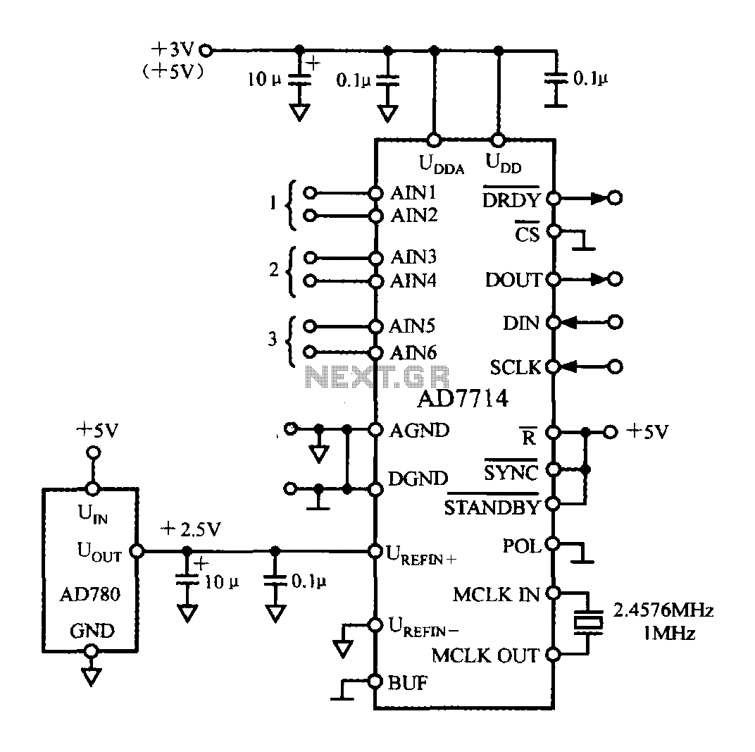
The typical application circuit for the AD7714 is illustrated in the accompanying figure. The UDD and UDDA terminals of the AD7714 can be connected to either a +3V or +5V power supply. The analog inputs are arranged as three...
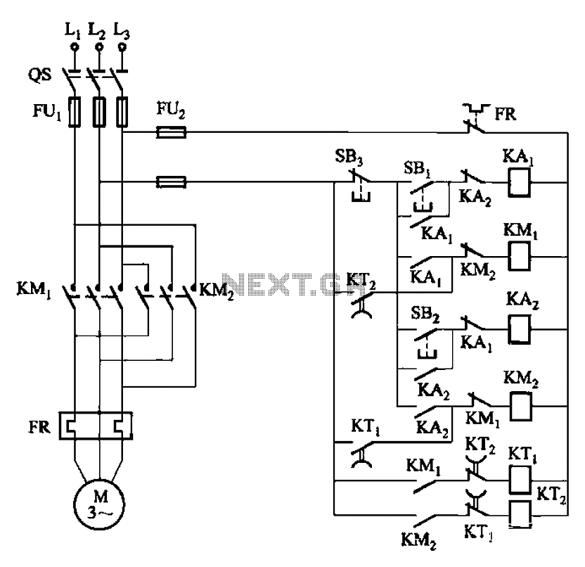
The circuit depicted in Figure 3-131 utilizes a relay instead of a speed control relay. It is designed to operate effectively in dusty environments and other challenging conditions. The circuit operates by employing a relay as a primary switching mechanism,...
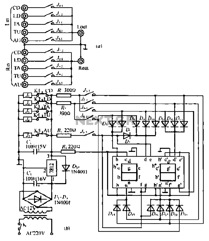
Can simulate the character Mu symbol. A bone dish SET code is needed that effectively manages the decimal point. An inverted J is required to open its mouth. Left foot circuit diagram. The project involves designing a circuit that simulates...
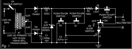
This document describes a simple triac tester circuit that can also be utilized for testing silicon-controlled rectifiers (SCRs) and both PNP and NPN transistors. The circuit operates on 3V DC, which can be derived from a Zener diode combined...
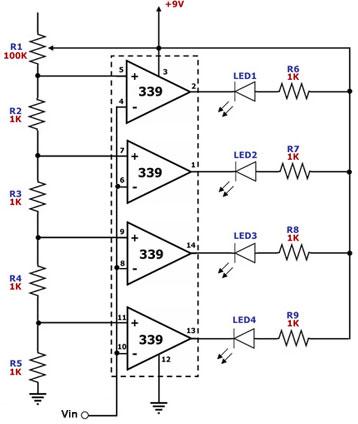
This circuit is designed as a simple LED bar graph voltmeter. Each operational amplifier in the LM339 quad package functions as a comparator, comparing the input voltage (Vin) to a series of fixed voltage levels that are proportional to...
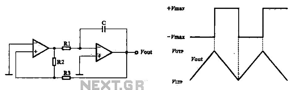
This circuit utilizes two operational amplifiers configured as triangular wave oscillators. It demonstrates a practical application of a relaxation oscillator that employs a voltage comparator to execute the switching function. The schematic in FIG. 2 illustrates the composition of...