
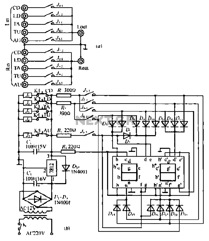
A five-way dual-channel audio switching circuit
The project involves designing a circuit that simulates the character Mu symbol, which is often represented in various applications, including animation and robotics. The core requirement is to create a bone dish SET code that can accurately manage decimal points, enhancing the precision of the output.
The circuit will utilize a microcontroller as the central processing unit, programmed to interpret the bone dish SET code. This code will dictate the position of various actuators that represent the character's features, including the mouth, which is controlled by an inverted J mechanism. The design should ensure that the inverted J structure can articulate effectively, mimicking the opening and closing motion of a mouth.
To achieve this, a motor driver circuit will be integrated to control the servos or stepper motors associated with the mouth mechanism. The left foot of the character will also be represented in the circuit, necessitating additional actuators and possibly sensors to provide feedback on position and movement.
The schematic will include power supply connections, ensuring that each component receives the appropriate voltage and current. Input pins will be designated for receiving commands from a user interface or external control system. Output pins will be connected to the motors that drive the mouth and foot movements.
In summary, the project requires a well-structured electronic schematic that encompasses a microcontroller, motor drivers, and actuators, all working in harmony to simulate the character Mu with precise movements and interactions. Can simulate the character Mu symbol, I need bone dish SET code which benefit s decimal point well Jl; inverted J to open his mouth. Left foot [ circuit diagram
Related Circuits
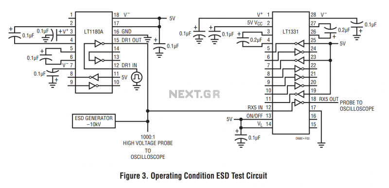
The machine model, commonly used for ESD testing in Japan, is a more severe ESD test. This model simulates metallic contact between the device under test and a charged body. The source capacitor is 200pF with no limiting resistor....
The circuit utilizes a dual sound multi-frequency encoding signal to modulate the emitted carrier frequency, forming a DTMF encoding wireless calling system. It incorporates the DTMF encoding circuit UM97085 and the decoding circuit YN9101 to create a micro wireless...
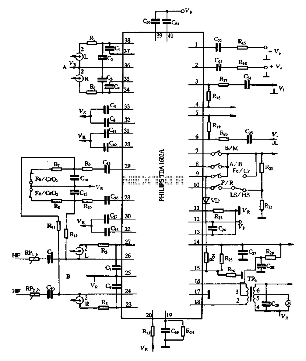
The A1602A is a 40-pin dual in-line package that functions as a playback preamplifier. It utilizes linear low-noise amplifiers with a voltage gain of 26.4 dB. Each channel has a separate discharge sound preamplifier, selected by an electronic switch...
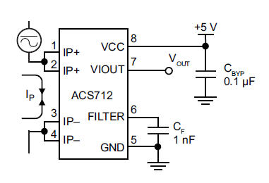
The primary component utilized is the ACS712 sensor from Allegro MicroSystems, designed for measuring current. It offers cost-effective and accurate solutions for AC or DC current sensing in industrial, commercial, and communication systems. A precise, low-offset, linear Hall sensor...
Electronic schematics collections provide a platform for discussions related to electronic circuit schematics, printed circuit board (PCB) diagrams, and various electronics projects. These collections serve as valuable resources for engineers, students, and hobbyists interested in electronics design and development. They...
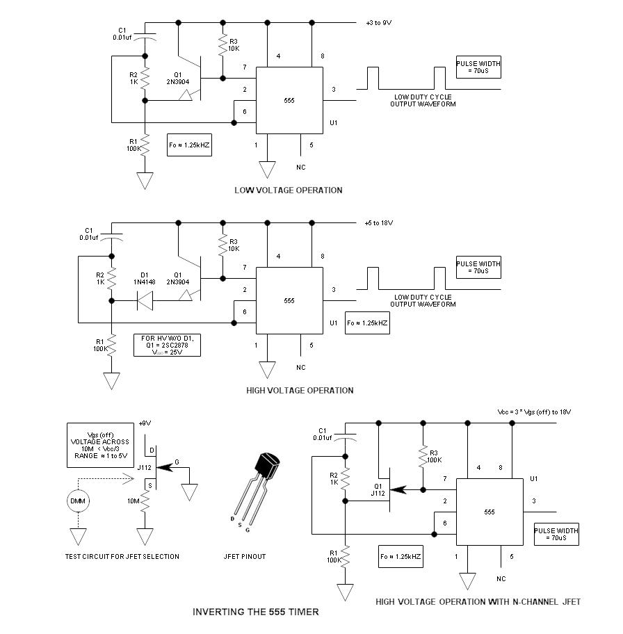
When using the 555 timer, the output polarity often appears to be incorrect, as the 555 typically cannot produce a duty cycle of less than 50%. This inverted 555 circuit is capable of generating duty cycles below 50%. The...
Warning: include(partials/cookie-banner.php): Failed to open stream: Permission denied in /var/www/html/nextgr/view-circuit.php on line 713
Warning: include(): Failed opening 'partials/cookie-banner.php' for inclusion (include_path='.:/usr/share/php') in /var/www/html/nextgr/view-circuit.php on line 713