
Using two operator triangular wave oscillator circuit
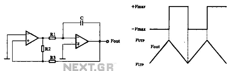
The circuit design involves two operational amplifiers (op-amps) arranged to generate a triangular wave output. The first op-amp functions as a voltage comparator, receiving a reference voltage and the output voltage from the triangular wave oscillator. The comparator toggles its output state between high and low based on the input voltages, effectively creating a switching function that drives the oscillation.
The triangular wave oscillator is typically configured using a resistor-capacitor (RC) network. The charging and discharging of the capacitor through the resistors create a linear ramp-up and ramp-down of voltage, which results in the triangular waveform. The frequency of oscillation can be adjusted by varying the values of the resistors and capacitors in the RC network.
In this configuration, the second op-amp can be used to further process the output signal, enabling functionalities such as signal conditioning or level shifting. The integration of these two op-amps allows for a versatile oscillator design that can be adapted for various applications, including signal generation, waveform shaping, and timing circuits.
Overall, this circuit exemplifies the effective use of operational amplifiers in generating oscillatory signals and demonstrates the principles of relaxation oscillation through the combination of voltage comparators and triangular wave generators.Using two operator triangular wave oscillator A practical application of the relaxation oscillator using a voltage comparator to perform the switching function, FIG. 2 is the use of composition operator triangular wave oscillator.
Related Circuits
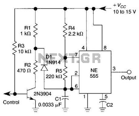
A 1-kHz gated oscillator with no long turn-on cycle is shown. R2, R3, and D1 preset the voltage on tuning capacitor C1 to a percentage of the supply voltage. The circuit described functions as a gated oscillator operating at a...
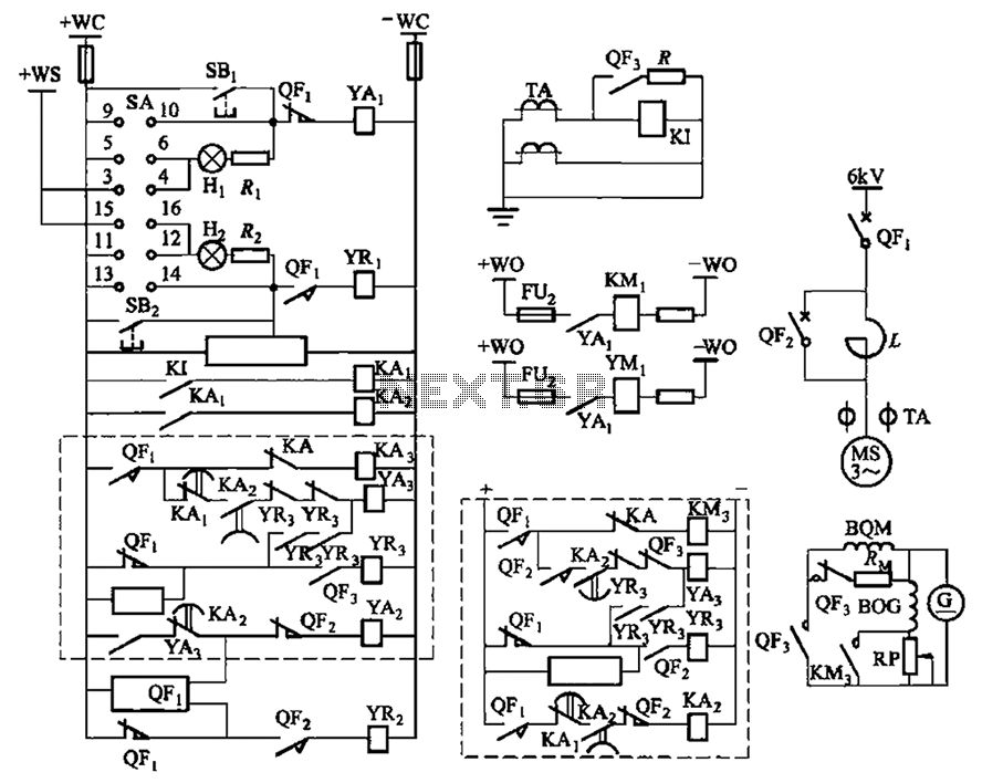
The circuit depicted in Figure 3-189 includes various components such as switch SA, closing button SBi, trip button SBz, de-excitation switch Yaa, and off trip coil YR3. The excitation switch contacts are represented by QF3, which serves as a...
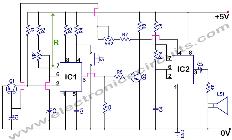
555 Timer with Audio Alarm Circuit. This circuit serves as a straightforward electronic timer equipped with an audio alarm feature. The 555 timer is a versatile integrated circuit widely used in various timer, delay, pulse generation, and oscillator applications. In...
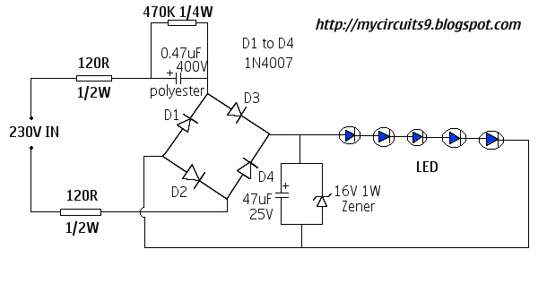
This document presents a 230V LED driver circuit that operates without a transformer. The circuit utilizes five LEDs, although the number can be increased as desired. The absence of transformers significantly reduces both the cost and size of the...
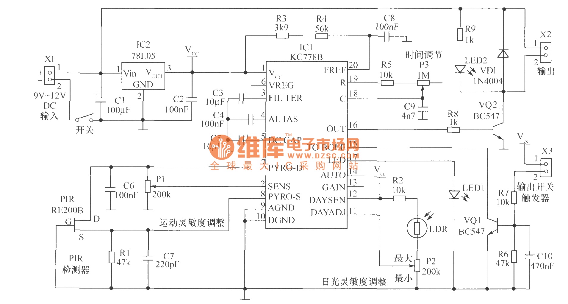
The core component of the motion detection circuit is the motion detection chip IC1 (KC778B). The signal frequency from the PIR sensor is low, ranging from 0.1Hz to 10Hz, while the bandwidth is quite broad, which the chip will...
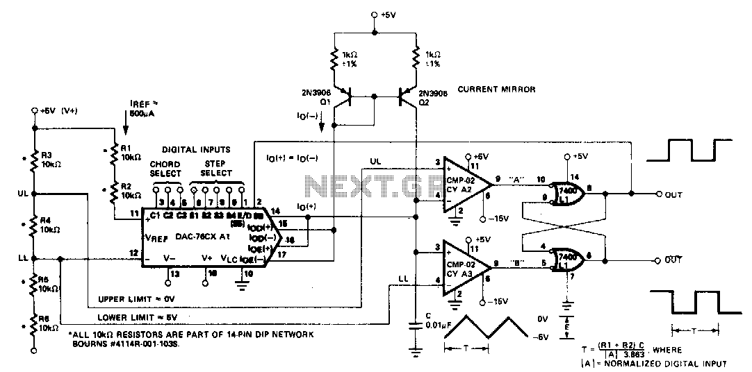
The microprocessor-controlled oscillator has a frequency range of 8159 to 1, covering from 2 Hz to 20 kHz. An exponential, current output integrated circuit digital-to-analog converter (DAC) functions as a programmable current source, alternately charging and discharging a capacitor...