
S/R Flip-Flop
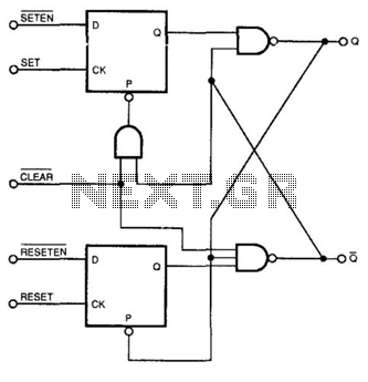
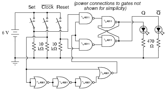
The described circuit functions as a hybrid flip-flop, leveraging the operational principles of both asynchronous S/R and edge-triggered JK flip-flops. The asynchronous S/R flip-flop is characterized by its ability to set and reset its output based on the levels of its inputs, while the edge-triggered JK flip-flop responds to the transitions of its clock input, providing a more controlled state change.
In this configuration, the circuit is designed to respond exclusively to the leading edge of the clock signals applied to its inputs. This means that the state of the outputs will only change when there is a rising edge detected, allowing for precise timing control. At all other times, the circuit maintains its previous state, effectively ignoring any changes in input levels until the next clock edge occurs.
The outputs of the D flip-flops, which are the primary components of this circuit, are typically in a high state. Upon receiving a clock pulse, the output will briefly transition to a low state, indicating that the flip-flop has registered an input change. This behavior is particularly useful in digital circuits where synchronization and timing are critical, as it allows for the reliable propagation of signals without the risk of false triggering from noise or spurious signals.
In practical applications, this circuit can be utilized in various digital systems, such as counters, shift registers, and memory storage devices, where the combination of asynchronous and synchronous characteristics provides enhanced functionality. The design considerations should include proper timing analysis to ensure that the flip-flops operate within their specified limits, especially regarding setup and hold times relative to the clock edges. Additionally, debouncing mechanisms may be necessary if the inputs are subject to mechanical switching or other forms of noise. This circuit combines the characteristics of an asynchronous S/R flip-flop and an edge-triggered JK flip-flop. It changes sta te on the leading edges of its inputs, and ignores the levels at all other times. In operation, outputs of both D flip-flops are normally high, going low for brief periods after seeing an edge at their respective clock inputs. 🔗 External reference
Related Circuits
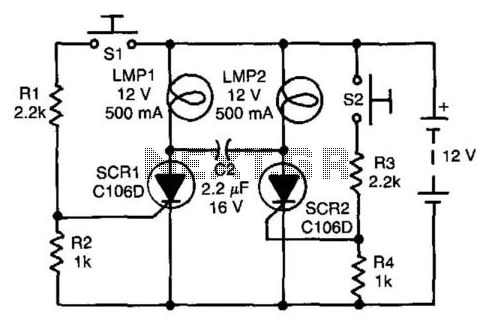
Assume first that SCR1 is on and SCR2 is off, allowing capacitor CI to be fully charged, with its LMP2 end positive. The state of the circuit can be altered by pressing switch S2. When SCR2 turns on, it...
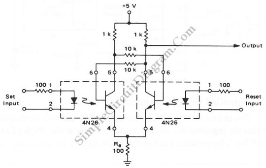
An RS flip-flop, also known as a reset-set flip-flop, is a type of stable multivibrator that has two inputs: reset and set. The output can exist in one of two stable states. The RS flip-flop is a fundamental building block...
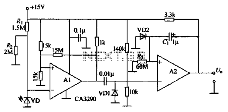
The circuit includes comparators A1 and A2, which function as a single-trigger timing device. When the light is interrupted, the current through photodiode VD changes. The output of A1 triggers A2, causing A2's output to go low and remain...
Electronics tutorial about bistable multivibrator, also known as the bistable flip-flop or two-shot multivibrator, constructed from transistors or logic gates. A bistable multivibrator is a fundamental electronic circuit that has two stable states and can maintain its state indefinitely until...
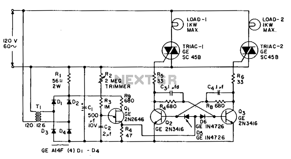
This application involves a static switch circuit where the control logic is implemented using a flip-flop, which is driven by a unijunction transistor. The flashing rate of the circuit can be adjusted, ranging from approximately 0.1 seconds to a...
The parts list specifies a ten-segment LED unit, but the illustration depicts two individual LEDs instead. This change is due to limited space on the breadboard for the switch assembly, two integrated circuits, and the bar graph. If space...