
The timing of the flip-flop circuit composed of a photodiode etc.

The circuit operates using a pair of comparators, A1 and A2, configured in a timing application. Comparator A1 monitors the current flowing through photodiode VD, which is sensitive to light. When the light source is interrupted, the current through the photodiode decreases, triggering the output of comparator A1. This output serves as a control signal for comparator A2, which subsequently switches its output state to low.
The low output from A2 is designed to persist for a predetermined duration of 60 seconds, which is established by the time constant of the associated resistor-capacitor (RC) network. This timing function is critical in applications where a delay is required before returning to a high state, allowing for the detection of transient interruptions in the light source.
Adjustments to the static resistance within the circuit can influence the sensitivity of the photodiode to varying light levels. However, it is essential to maintain the protection ratio to ensure the circuit's stability and reliability. The design incorporates provisions for anti-bias voltage, which helps to mitigate fluctuations that could lead to erroneous triggering of the comparators.
The components used in this circuit, as illustrated in Figure 3-20, are standard and do not have any special requirements, allowing for ease of implementation. The timing circuit's activation through a photodiode or similar device provides flexibility in various applications, making it suitable for environments where light interruption needs to be monitored and responded to appropriately. This configuration is beneficial in security systems, automated lighting controls, and other similar applications where light detection is crucial. Circuit, the comparator Al, A2 is a single trigger timing device. When the light is interrupted, photodiode VD of current changes. Al output trigger A2, A2 output goes low and 60s (the Island and cl Huan set) remains within the low level. Horse and surprised static resistance change can change the VD sensitivity to light tincture but its ratio to protect unchanged so as V) provides some anti- bias voltage. (2) Component parameters: Component selected in Figure 3-20 shows the new, no special requirements. (3) As shown in the timing circuit is triggered by a photodiode or the like of
Related Circuits
There is an advantage in using continuously active PWM signals. The main reason is that the asynchronous frequencies of the PWM core and microcore can sometimes result in a shortened PWM pulse. The servo recognizes this as a command...
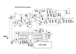
This is a straightforward high-quality PLL FM transmitter with a typical output power of 5 W and a no-tune design. It features RDS/SCA input and audio/MPX input with optional pre-emphasis and can operate with or without a stereo encoder....
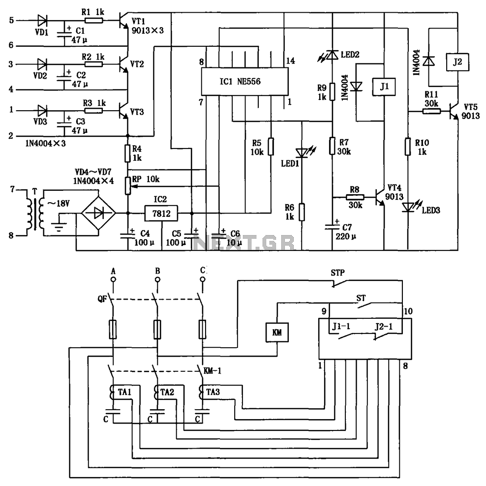
The circuit depicted is utilized in a power supply system to promptly disconnect the power supply in the event of an over-voltage condition during either the grid's on or off phase, thereby protecting the power capacitors. This circuit serves a...
Have you ever attempted to copy a commercially produced video only to end up with a distorted and jumpy image? If so, then you have run afoul of MacroVision. MacroVision is the most popular copy protection scheme used on...
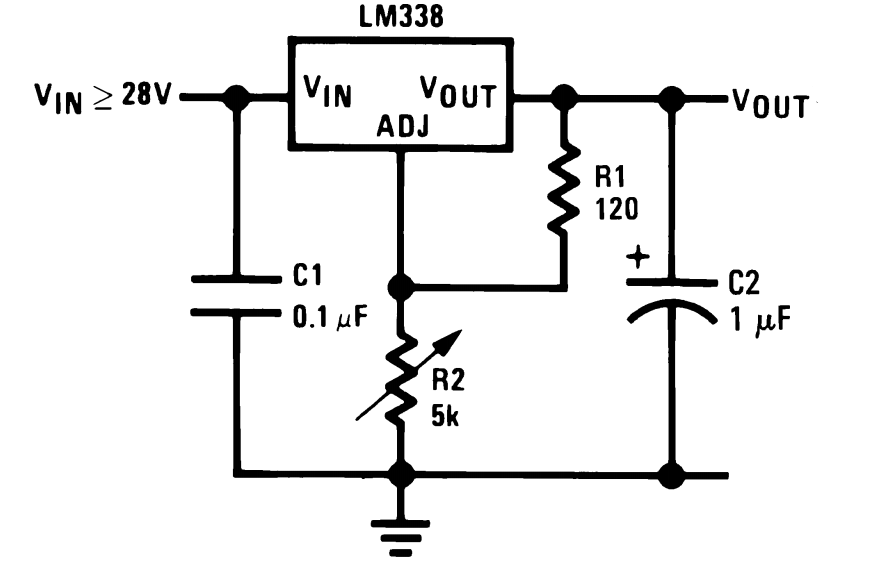
The LM338 integrated circuit (IC) from Texas Instruments is a versatile component that can be configured in various ways to create high-quality power supply circuits. The first circuit demonstrates the typical wiring format around the IC, providing an adjustable...
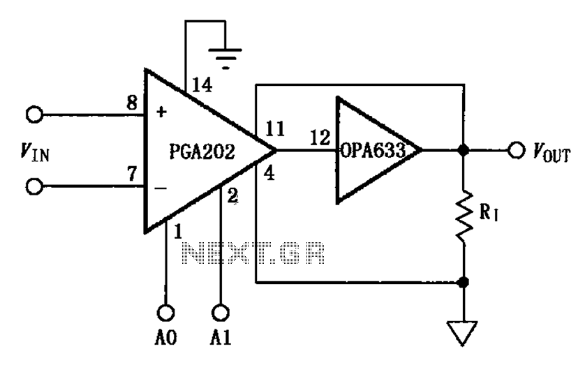
The figure illustrates a current boosting circuit configuration utilizing the PGA202 and OPA633 operational amplifiers. This circuit enhances the output current capability of the PGA202 operational amplifier, leveraging the performance characteristics of the OPA633 to achieve a higher output...