
SAA1042 stepper motor control circuit
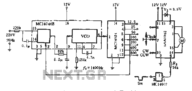
The SAA1042 stepper motor driver operates with a supply voltage of 12V, making it suitable for applications requiring precise control of motor positioning. The selection of a 200mA phase winding current indicates that the motor is designed to operate efficiently at this current level, ensuring optimal performance while minimizing power consumption and heat generation.
The resistor RE, valued at 56kΩ, plays a crucial role in setting the appropriate biasing conditions for the driver circuit, ensuring stable operation and preventing excessive current draw that could lead to overheating or damage. The integration of the NAND gate MC14007 facilitates logic operations essential for controlling the stepper motor's direction and stepping sequence.
The clock signal, generated by the MC14046 and MC14024 PLL frequency synthesizer, is vital for the timing of the stepper motor's operation. By producing a frequency range of 12.5 to 500Hz, the system allows for a variety of stepping speeds, enabling users to select from seven distinct gear ratios. This flexibility is particularly beneficial in applications requiring different levels of torque and speed, enhancing the overall versatility of the stepper motor system.
The design exemplifies a well-integrated approach to controlling stepper motors, utilizing standard components to achieve reliable and efficient motor control in various applications, from robotics to automated machinery.A typical application example shown, SAA1042 12V stepper drive motivation, phase winding current is taken as 200mA. Choose from the RB Figure 5-10, taking RE = 56kfl. It is connected to the output of NAND gate MC14007. Figure 5-9 clock by MC14046 and MC14024 PLL frequency synthesizer composition produced. Stepping clock in 12. 5- SOOHz carve seven gear selection.
Related Circuits
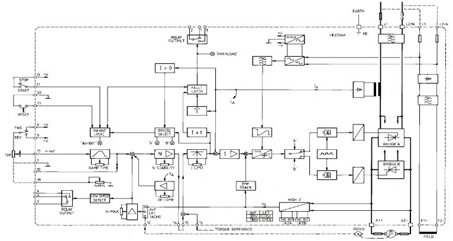
This figure represents the 4Q2 DC Motor Speed Controller Circuit Block Diagram, designed for comprehensive control of conventional shunt-wound and permanent magnet motors with a capacity of up to 75 kW, as specified in the datasheet. This type of...
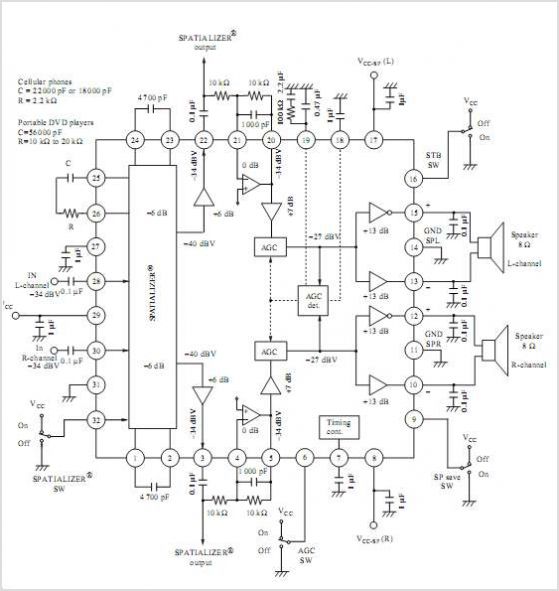
AN12979A is a stereo BTL amplifier that includes an AGC circuit to prevent clipping at the speaker output. This integrated circuit (IC) can perform mode changes via the I2C bus control system, allowing for functions such as toggling the...
Active power factor correction stabilizes the electrical demand of a device to provide optimal power factor characteristics for various types of loads. To comply with power factor regulations, a cost-effective solution should be designed. In many applications, the requirement...
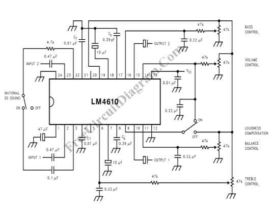
The LM4610 utilizes a DC signal to manage the tone (bass/treble), volume, and balance circuits. The benefits of employing DC control include the ability to operate in mono mode. The LM4610 is an integrated circuit designed for audio applications, specifically...
The danger always exists when fuel gases such as propane or natural gas are confined to a small area. The toxic gas alarm utilizes a tin-oxide semiconductor. A coil of thin wire is heated by a 12 V battery...

Capacitor start single-phase induction motor circuit configuration, in order to form a two-phase rotating magnetic field, starting winding and capacitor in series, the same magnetic field can be formed automatically. The capacitor start single-phase induction motor utilizes a specific circuit...