
Sample and Hold Circuit Using CA3140 Op-Amp
The sample-and-hold circuit is a crucial component in analog-to-digital conversion systems, allowing for the temporary storage of analog signals for subsequent processing. This circuit captures the voltage of an input signal at a specific moment and holds it steady for a defined period, enabling accurate measurements.
In this particular design, the CA3140 operational amplifier serves as the readout amplifier, providing high input impedance and low output impedance, which is essential for interfacing with the memory capacitor. The CA3080A, a current feedback amplifier, is incorporated to enhance the performance of the circuit, particularly in terms of speed and bandwidth.
The operation of the sample-and-hold circuit can be divided into two phases: the sample phase and the hold phase. During the sample phase, the circuit captures the input voltage, which is then stored on the memory capacitor. The switch controlling this phase is typically a high-speed analog switch that ensures minimal charge injection and distortion.
Once the sample phase is complete, the circuit transitions to the hold phase. In this phase, the switch opens, isolating the memory capacitor and maintaining the voltage level for the duration of the hold time. The output from the CA3140 can then be processed or fed into an analog-to-digital converter for further analysis.
The choice of components, such as the CA3140 and CA3080A, reflects a focus on achieving high accuracy and stability in the circuit operation. The design also considers factors like leakage currents and capacitor dielectric absorption, which can affect the hold time and overall performance of the circuit. Proper layout and component selection are essential to minimize noise and ensure reliable operation in various applications.The schematic diagram below shows a very simple sample-and-hold circuit using the CA3140 as the readout amplifier for the memory capacitor. The CA3080A is used. 🔗 External reference
Related Circuits
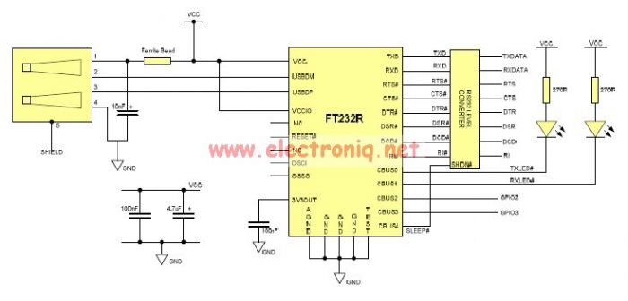
This USB to Serial RS232 adapter is highly beneficial in scenarios where a device with RS232 needs to be connected to a computer lacking an RS232 port but equipped with a USB port. Utilizing the FT232BM chip produced by...
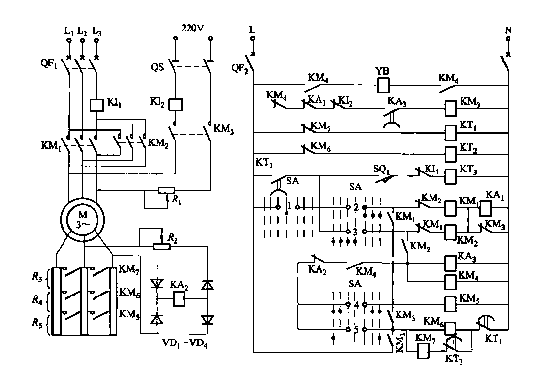
Figure 3173 illustrates a control circuit for a wound rotor induction motor that enables mechanical braking, dynamic braking, and reverse braking functions. The circuit includes various components such as relays, contactors, and time relays to manage the motor's speed...
This modified Hartley oscillator can be utilized to attract new friends or serve as a replacement doorbell. The modified Hartley oscillator is a type of electronic oscillator that generates a continuous waveform, typically a sine wave, using an LC (inductor-capacitor)...
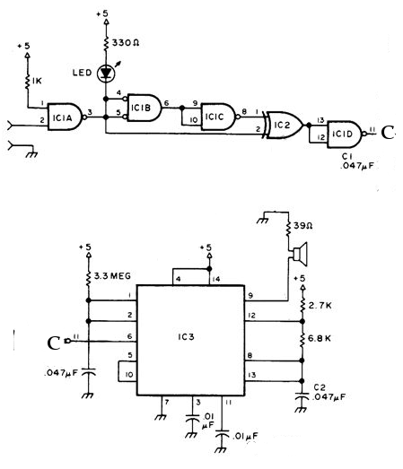
The NE556 timer can function as an indicator for the static state of a digital logic audible terminal. An audible logic probe is beneficial for visually inspecting a component while simultaneously checking the logic state at another point far...
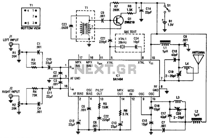
In this application, a BA1404 is utilized to generate an FM MPX baseband signal. This signal modulates a crystal oscillator (Q3) through a dual varactor series modulator. This transmitter can be used to play CD audio on an existing...
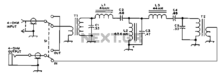
The circuit provides an 8-ohm output for connecting communication receivers and low-impedance speakers or headphones, featuring harmful interference suppression for continuous random voice transmission. The passband ranges from 55 to 2530 Hz with a 3 dB bandwidth. Inductors L1...