
Electronic Canary circuit
The modified Hartley oscillator is a type of electronic oscillator that generates a continuous waveform, typically a sine wave, using an LC (inductor-capacitor) circuit. The fundamental operation of the Hartley oscillator relies on the feedback mechanism provided by the inductors and capacitors to sustain oscillations.
In this configuration, the circuit includes two inductors (L1 and L2) and a capacitor (C). The inductors are connected in series, and the feedback is taken from the junction between them. The oscillation frequency can be determined using the formula:
\[ f = \frac{1}{2\pi \sqrt{(L1 + L2)C}} \]
Where \( f \) is the frequency of oscillation, \( L1 \) and \( L2 \) are the values of the inductors, and \( C \) is the capacitance.
To implement this oscillator as a doorbell, the output can be connected to a small speaker or piezoelectric buzzer to produce sound. The circuit may also include a transistor to amplify the output signal, ensuring that the sound produced is loud enough to be heard clearly.
Additional components may include a power supply, typically a battery or DC power source, and a switch to activate the oscillator when someone presses the doorbell button. The oscillator's frequency can be adjusted by varying the values of the inductors and capacitor, allowing customization of the sound produced to suit personal preferences.
This versatile circuit not only serves as a doorbell but can also be used in various applications where sound generation is required, making it an excellent choice for hobbyists and electronics enthusiasts.Feeling chirpy? Attract new friends with this modified hartley oscillator. You could also use it as a replacement doorbell.. 🔗 External reference
Related Circuits
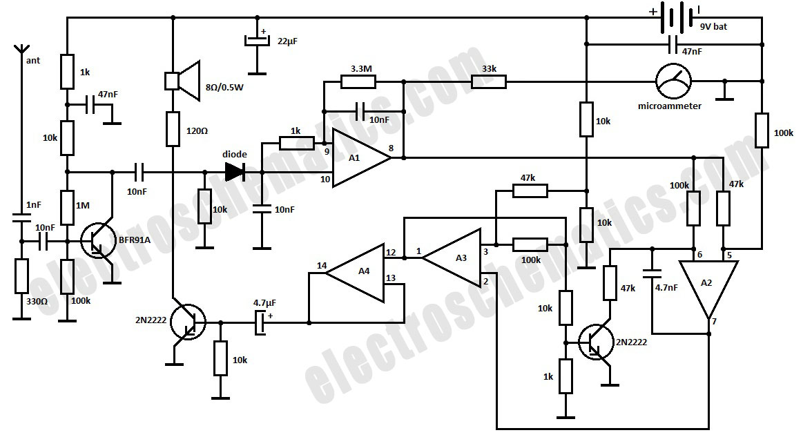
This is a simple RF bug detector designed to identify spy bugs, capable of operating up to 2 GHz. Below are some essential components required for this circuit. The RF bug detector circuit functions by utilizing radio frequency signals...
The chip in the center with small bullet holes is likely proprietary. It is possible to salvage a few components from it, although understanding the circuit is not necessary for this purpose. Additionally, it is confirmed that the device...
The CDI ignition circuit generates a spark from an ignition coil by discharging a capacitor across the primary winding of the coil. A 2µF capacitor is charged to approximately 340 volts, with the discharge process controlled by a silicon-controlled...
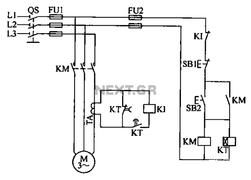
A three-phase electric motor overcurrent protection circuit. This example circuit utilizes a transformer to monitor the current, ensuring that the currents in the three-phase motor do not exceed normal operating levels. When the current exceeds the set threshold, the...
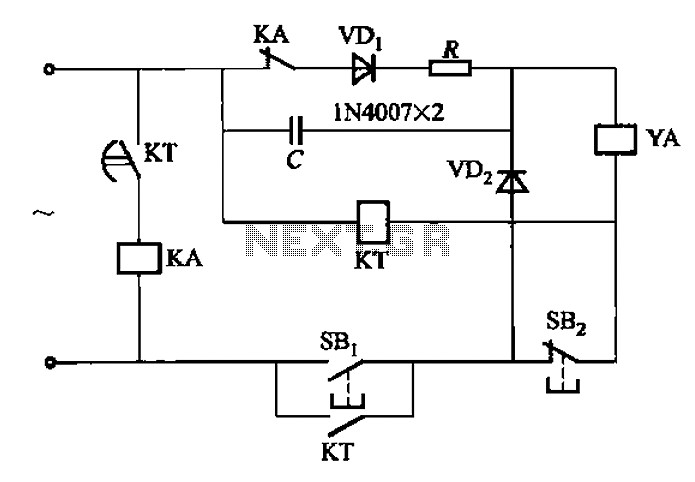
AC solenoid DC circuit operation operates similarly to a DC contactor circuit, but the AC solenoid pull circuit is illustrated in the provided figure. The capacitance C is generally between 1-10 microfarads (µF), with a minimum of 20 microfarads...
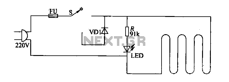
The circuit of electric blankets is controlled by switch S. When switch S is fully engaged, the entire supply voltage of 220V is applied to the heating wire, resulting in a high-temperature state. When a lower temperature is desired,...
Warning: include(partials/cookie-banner.php): Failed to open stream: Permission denied in /var/www/html/nextgr/view-circuit.php on line 713
Warning: include(): Failed opening 'partials/cookie-banner.php' for inclusion (include_path='.:/usr/share/php') in /var/www/html/nextgr/view-circuit.php on line 713