
Sawtooth to triangle converter for oscillator
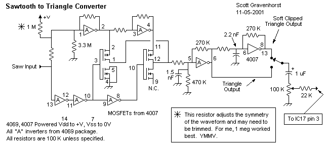
The circuit described functions as a wave shaper that operates with a sawtooth waveform input, achieving a transformation of the waveform characteristics. The input signal should ideally span from Vss (-12 volts) to Vdd (0 volts), ensuring that the waveform is centered between the power supply rails. The circuit utilizes a 4069 Voltage Controlled Oscillator (VCO), which is known for its versatility in generating various waveforms, including sawtooth.
The design incorporates two linear mode gates, positioned at the upper section of the schematic. These gates produce both an inverted and a non-inverted version of the sawtooth input, which is essential for the subsequent processing stages. Below these gates, three logic gates serve as a comparator, detecting when the sawtooth signal reaches the midpoint between the two voltage rails. This comparator action is critical as it determines the switching behavior of the circuit.
The 4007 IC is employed to implement two P-channel MOSFETs. These devices are responsible for selecting either the inverted or non-inverted sawtooth signal based on the current state of the sawtooth waveform. As the sawtooth progresses through its cycle, the MOSFETs alternate their selection, which results in a ramp signal that reverses direction every half cycle. This behavior is significant in creating a dynamic output waveform.
The output of this circuit is sensitive to any imperfections in the input sawtooth signal. Any irregularities will manifest in the output waveform, thus highlighting the importance of a clean input signal for optimal performance. The circuit also includes a linear mode gate positioned at the far right, which contributes soft clipping to the output. This soft clipping process alters the triangle wave generated by the circuit, producing a waveform that resembles a sine wave. The resulting output is characterized by a smoother harmonic profile, with fewer harmonics compared to a standard triangle wave.
In terms of power supply requirements, all integrated circuits (ICs) are powered with Vdd set to 0 volts and Vss set to -12 volts. It is essential that all ground symbols in the schematic are connected to -12 volts, while all positive voltage symbols are directed to ground, ensuring proper operation of the entire circuit. This configuration is crucial for maintaining the intended functionality of the wave shaping process.This wave shaper needs an input saw that goes from Vss to (ideally) Vdd. It works well with the 4069 VCO designed by Ren? Schmitz. Any saw will work as long as the wave is centered halfway between the rails. It works as follows: The upper set of 2 linear mode gates provide an inverted and noninverted copy of the saw. The 3 logic gates at the bottom provide a sort of comparator that switches at halfway between the rails.
The 4007 provides 2 P-MOSFETs that alternately select the inverted or noninverted saw signal depending on where the saw is in it's cycle. This causes the ramp to reverse directions every half cycle. Any imperfection in the saw will show up in the resulting output. The linear mode gate furthest to the right provides soft clipping that turns the triangle wave into something like a sine wave. It sounds like it has fewer harmonics than the triangle. Power all ICs: Vdd = 0 volts, Vss = -12 volts. All ground symbols on schematic will go to -12 volts and all +V symbols go to ground. 🔗 External reference
Related Circuits
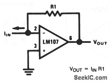
This basic circuit feeds the input current directly into the summing node (pin 2), causing the op-amp output to adjust and extract the same current from the summing node through resistor R1. The scale factor of the circuit is...

This design circuit functions as a sine wave oscillator, providing both sine and square wave outputs across a frequency range from below 20 Hz to above 20 KHz. The oscillation frequency can be easily adjusted by varying a single...
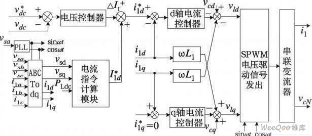
The demand for high-quality electric energy in modern industrial development is increasing, making it essential to provide safe and reliable green power to energy consumers. Uninterruptible Power Supplies (UPS) are crucial for improving electric energy quality and ensuring the...
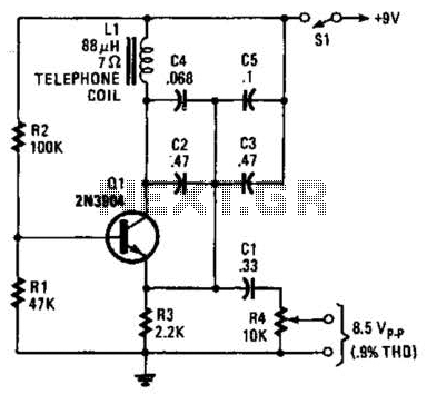
An 88 mH surplus telephone toroidal coil is utilized in a 1 kHz oscillator. It can provide up to 8 V peak-to-peak into a high-impedance load. The total harmonic distortion (THD) is 0.9%. The circuit employs an 88 mH toroidal...
The AD654 is a monolithic voltage-to-frequency (V/F) converter that comprises an input amplifier, a precision oscillator system, and a high-current output stage. A single resistor-capacitor (RC) network is all that is needed to configure any full-scale (FS) frequency up...
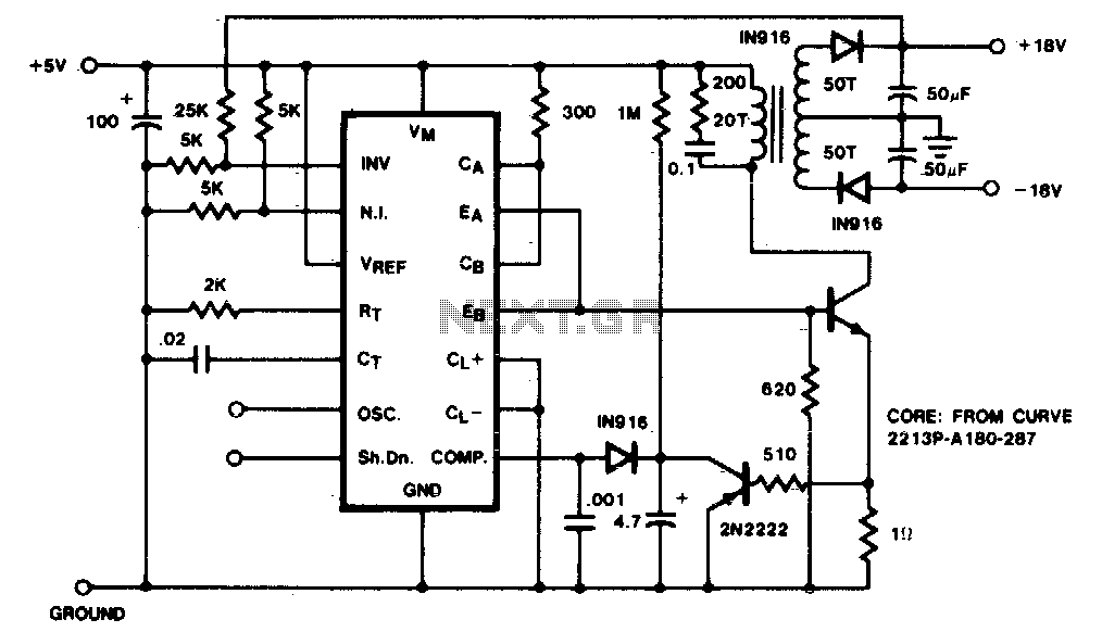
A low-current flyback converter is utilized to generate ±15 volts at 20 mA from a +5 volt regulated line. The reference generator in the SG1524 is not used, with the input voltage serving as the reference. Current limiting in...