
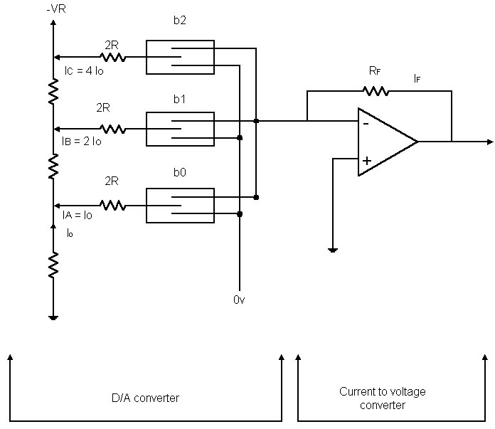
Basic current to voltage converter
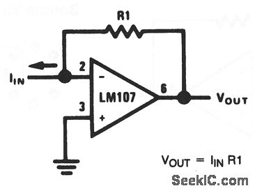
The described circuit operates as a current-to-voltage converter, utilizing an operational amplifier (op-amp) in a summing configuration. The input current (IIN) is introduced at the summing node, which is connected to the inverting input of the op-amp. The op-amp is configured in a feedback loop with resistor R1, which plays a crucial role in determining the output voltage (VOUT). The relationship between the output voltage and input current is linear, making this circuit ideal for precise current measurements.
In this design, the op-amp amplifies the difference between the input current and the bias current, effectively minimizing the impact of the bias current on the output. The output voltage can be monitored to indicate the magnitude of the input current directly, allowing for easy interpretation of the measurement. The scale factor, defined by R1, can be selected based on the desired output voltage range for specific applications. For example, a larger R1 value will yield a higher output voltage for the same input current, which may be beneficial in applications requiring greater voltage levels.
This circuit can be implemented in various measurement systems, where accurate current readings are essential. The simplicity of the design, combined with the op-amp's high input impedance and low output impedance, ensures that the circuit does not significantly load the source being measured, preserving the integrity of the current measurement. Additionally, the circuit can be expanded with additional components, such as filters or additional op-amps, to enhance performance or adapt to specific measurement conditions.With this basic circuit, the input current is fed directly into the summing node (pin 2) and the op-amp output changes to extract the same current from the summing node through R1. The scale factor of this circuit is R1 volts per amp. That is, the output voltage is equal to the input current timesR1. The only conversion error in this circuit is Ib ias, which is summed algebraically with IIN. The basic circuit can be used to measure current directly because: IIN =VOUT/R1. For example, if VOUT is 1 V (or 1000mV), and R1 is 100 ©, IN = 10mA. 🔗 External reference
Related Circuits
The circuit presented here can convert a single-ended supply voltage into a balanced set of supply voltages. This is achieved without the use of difficult-to-obtain, exotic integrated circuits. All components utilized in the circuit are common and likely available...
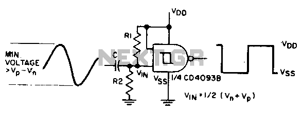
The sine input is AC coupled by capacitor C. Resistors Rl and R2 bias the input midway between Vn and Vp, which are the input threshold voltages. This configuration is designed to provide a square wave at the output. The...
This circuit is not a novelty, but it proved so useful, simple and cheap that it is worth building. When the positive (Red) probe is connected to a DC positive voltage and the Black probe to the negative, the...
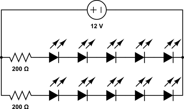
A 12V power supply is available, and there is a need to power LEDs with a forward voltage of 2V. It is questioned whether only six LEDs can be powered or if the cathode of one LED can be...
A basic circuit of the 89C2051 shown here can be made easily using point-to-point soldering with a universal PCB. Use an ordinary 20-pin socket, do not use a circle-pin socket. D1 is a small dot LED. U2 can be...
Before examining the various analog-to-digital (A-D) and digital-to-analog (D-A) conversion processes, it is useful to review the properties of each type of representation; in particular, this may help select the representation most suited to the problem at hand. An...