
Sawtooth Wave Oscillator Using 555 IC

The sawtooth wave oscillator utilizing the 555 timer IC operates in astable mode, generating a continuous sawtooth waveform. The circuit consists of the 555 timer, resistors, capacitors, and a power supply. The frequency and amplitude of the output waveform can be adjusted by varying the resistor and capacitor values.
In the astable configuration, the 555 timer alternates between its high and low states, charging and discharging the timing capacitor. The output waveform rises linearly during the charging phase and falls rapidly during the discharging phase, creating the characteristic sawtooth shape.
The timing capacitor (C1) is charged through two resistors (R1 and R2), and the discharge occurs through R2. The frequency of oscillation (f) can be calculated using the formula:
\[ f = \frac{1.44}{(R1 + 2R2) \cdot C1} \]
Where R1 is the resistor connected to the positive supply voltage, R2 is connected to the discharge pin, and C1 is the timing capacitor. The duty cycle can be adjusted by changing the ratio of R1 to R2, which in turn affects the slope of the rising edge of the sawtooth waveform.
The output of the 555 timer can be connected to other circuitry for signal processing, modulation, or as a clock signal for digital devices. The sawtooth wave is particularly useful in applications such as waveform generation, audio synthesis, and as a timing reference in various electronic circuits.
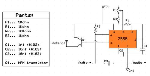
Proper decoupling capacitors should be placed near the power supply pins of the 555 timer to ensure stable operation, and the circuit should be designed to handle the required load based on the intended application.Sawtooth wave oscillator? circuit can be implemented using several methods, here we present one design that employs 555 IC.? Here is the schematic diagram of. 🔗 External reference
Related Circuits
This is a driving relay circuit utilizing a 555 integrated circuit (IC). The circuit is designed to control a relay and prevent the 555 IC from becoming unresponsive by employing inductive feedback. The coil is safeguarded. The driving relay circuit...
The SE555/NE555 timer was first introduced by Signetics Corporation around 1971. The pin connections and their functions are as follows: Pin 1 (Ground) is the most-negative supply potential and is typically connected to circuit common when powered by positive...
Planning to base a QRP transmitter on an instructables project, utilizing a large collection of 555 integrated circuits available. The issue is that this transmitter is designed to operate slightly below the commercial AM band. The goal is to...
This circuit is designed for children's entertainment and can be installed on bicycles, battery-powered cars, motorcycles, as well as on models and various games and toys. When switch SW1 is positioned as depicted in the circuit diagram, it generates...
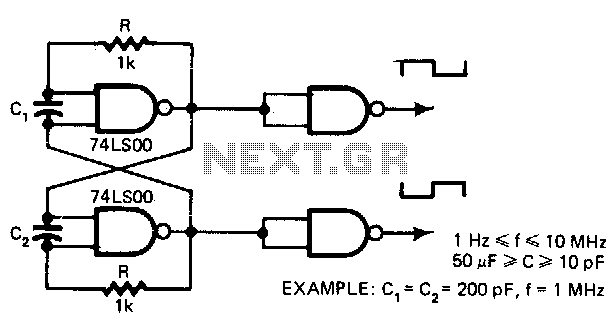
This low-cost oscillator is consistently self-starting and capable of operating from over 1 Hz to 10 MHz, requiring only five components. The period of oscillation can be calculated using the relationship: P = 5 x 10^3 C seconds when...

Using Rl, R7, and D1 to preset CI to one third of the supply voltage. This circuit avoids a longer first cycle period than subsequent cycles. The circuit described involves the use of resistors Rl and R7 along with diode...