
What determines the transmit frequency in this 555-based transmitter
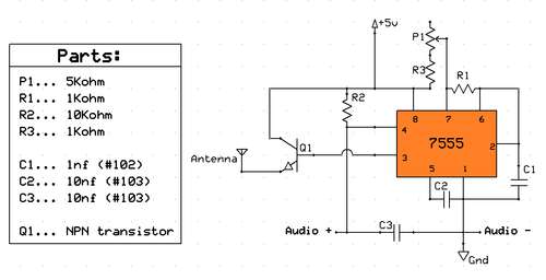
The project involves designing a QRP (low-power) transmitter using the versatile 555 timer IC, which is favored for its ease of use and availability. The original design operates below the commercial AM band, necessitating modifications to achieve the desired frequency of approximately 1.8 MHz, which is the lower end of the 160-meter amateur radio band.
To set the operating frequency of the transmitter, the 555 timer can be configured in astable mode. In this configuration, the frequency is determined by the resistors and capacitors connected to the timer. The frequency (f) can be calculated using the formula:
f = 1.44 / ((R1 + 2R2) * C)
Where R1 and R2 are the resistances in ohms, and C is the capacitance in farads. To achieve the target frequency of 1.8 MHz, appropriate values for R1, R2, and C must be selected. For instance, using a capacitor value in the range of 10 nF and adjusting R1 and R2 accordingly can help reach the desired frequency.
Additionally, it is important to implement a low-pass filter following the output stage of the transmitter to minimize harmonics, which can interfere with other communications. A simple LC filter can be constructed using an inductor and a capacitor to ensure that only the fundamental frequency is transmitted.
In terms of power supply, a suitable voltage regulator may be used to provide a stable voltage to the 555 timer and associated components, ensuring reliable operation. Furthermore, a suitable antenna matching network could be incorporated to optimize the power transfer from the transmitter to the antenna, enhancing transmission efficiency.
Finally, safety precautions should be emphasized, especially when teaching students about RF transmission, to ensure compliance with local regulations and to promote responsible operating practices. This project not only serves as a practical application of electronics but also fosters an understanding of amateur radio principles among students.Planning on basing a QRP transmitter off of this instructables project, seeing as I have a veritable plethora of 555 ics in my shack toolbox. The problem is, this transmitter is designed to operate a bit below the commerical AM band. How is the general operating frequency being set I`d like to get it set around the 1. 8 mhz band (160 meters). Much help is appreciated, as I`m going to use this to teach the other kids in the ham radio club at my school how to build basic transmitters. Picture of circuit: 🔗 External reference
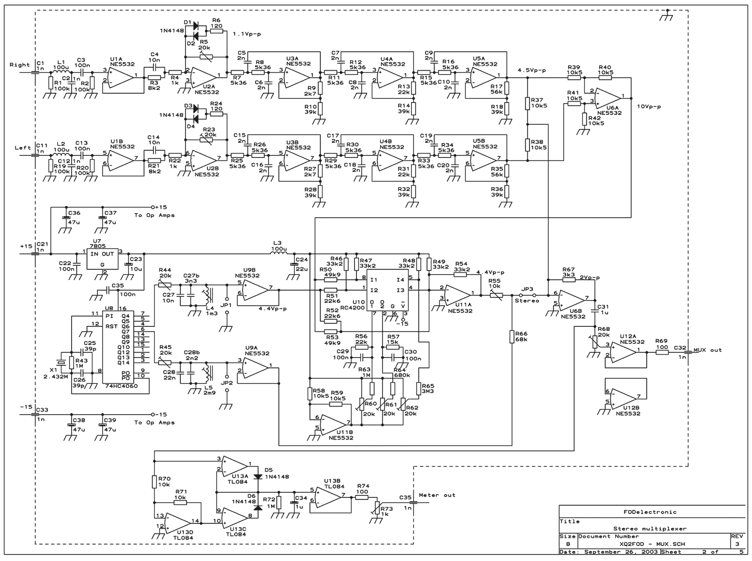
Related Circuits
This transmitter operates in the shortwave range from 6 MHz to 22 MHz. Coil L1 serves as the shortwave oscillating coil for the 6SA7 vacuum tube and is commercially available. Capacitor C1 is a variable capacitor with a capacitance...
This wireless headphone transmitter ensures a reliable connection over a distance of 2 meters. The oscillator frequency ranges between 1750 KHz and 3500 KHz, utilizing a ferrite bar as the antenna. IC1 amplifies the audio signal, while TC1 serves...
The transmitter described here includes an additional RF power amplifier stage following the oscillator stage, which increases the output power to 200-250 milliwatts. When connected to a properly matched 50-ohm ground plane antenna or a multi-element Yagi antenna, this...
This transmitter was designed from the ground up to provide very high sound quality, coupled with excellent frequency stability, reliability, etc. It can be used as a standalone transmitter to serve a medium-sized town, or as an exciter to...
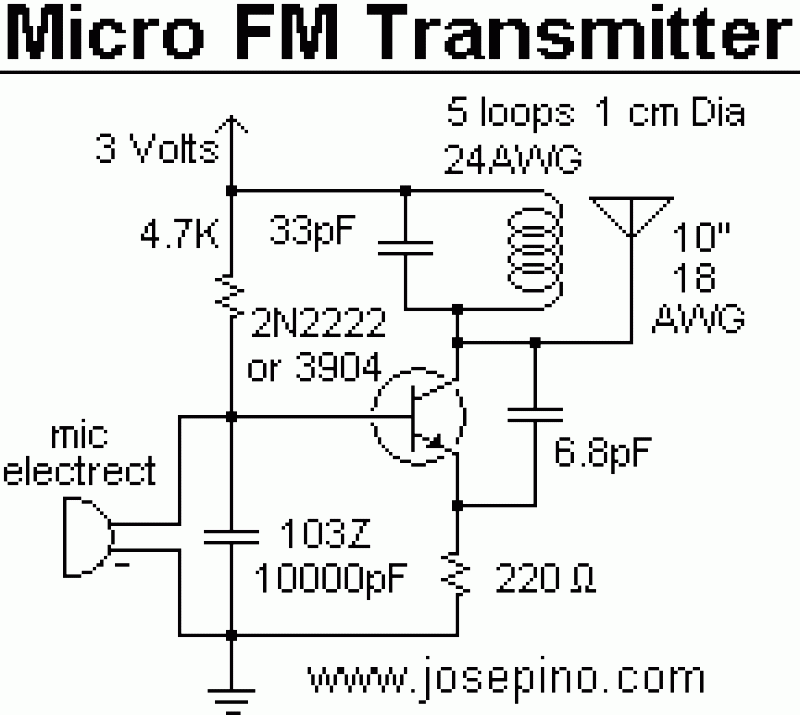
This is the basic FM transmitter that I built. In theory, according to electronics, it shouldn't work but works fine and is very sensitive. It can transmit the signal up to 45 yards (about 40 meters). A sensitive FM...
A low-frequency test oscillator designed for testing tone controls and conducting experiments. The low-frequency test oscillator serves as a versatile tool in audio engineering, particularly for evaluating tone control circuits and facilitating various audio experiments. This device generates sinusoidal waveforms...