
Driving Relay with 555 IC
The driving relay circuit based on the 555 IC operates in a monostable or astable mode, depending on the configuration. The primary function of this circuit is to control a relay, which can switch larger loads than the IC can handle directly. The 555 IC is favored for its reliability and versatility in timing and switching applications.
In this circuit, the relay's coil is connected to the output pin of the 555 IC. When the IC outputs a high signal, the relay is energized, closing its contacts and allowing current to flow through the load. The inductive feedback mechanism is crucial in this design, as it prevents the 555 IC from hanging or becoming unresponsive due to the back EMF generated when the relay coil is de-energized. A flyback diode is typically placed in parallel with the relay coil to provide a path for the inductive kickback, thus protecting the 555 IC from voltage spikes.
The circuit may include additional components such as resistors and capacitors to set the timing characteristics of the 555 IC, determining how long the relay remains energized. Proper selection of these components is essential for achieving the desired operational behavior. The input to the 555 IC can be triggered by various means, such as a push button or another electronic signal, allowing for flexible application in different scenarios.
Overall, this driving relay circuit is an effective solution for controlling higher power loads while ensuring the reliable operation of the 555 IC through inductive feedback protection.This is a Driving Relay circuit using 555 IC. The circuit is used to drive a relay to avoid 555 hangs up, it uses an inductive feedback. The coil is prevented.. 🔗 External reference
Related Circuits
To achieve a 50% duty cycle using a 555 timer IC, two diodes can be employed to isolate the charging and discharging paths. Alternatively, it is also possible to configure the circuit without diodes. The 555 timer IC is a...
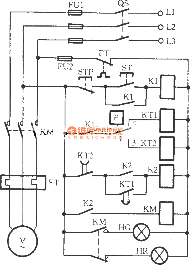
The circuit utilizes two time relays, KT1 and KT2, which are connected in series with the contacts of an electric contact pressure gauge (SP). This configuration helps to mitigate issues such as tremors or sparking that may occur due...
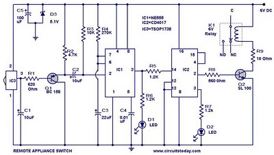
555 Timer TV Remote Controlled Home Appliance Circuit Diagram. Features: 555 timer IC to avoid fast switching. You can only switch the circuit. The 555 timer integrated circuit (IC) is a versatile component widely used in various electronic applications, including...
A type of relaxation oscillator comprising two stages that are interconnected such that the input of one stage is derived from the output of the other. This configuration essentially consists of two amplifiers cross-coupled with regenerative feedback in its...
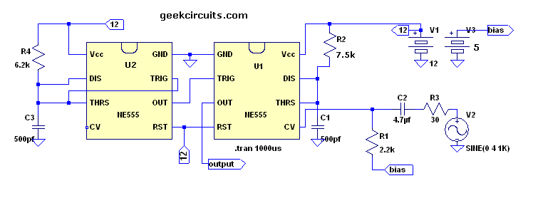
This text continues the discussion on a Class D amplifier utilizing a 555 timer chip. In reviewing previous schematics, the inclusion of a second 555 timer (U2) raises questions. The primary function of U2 is to provide a constant...

This is a simple smoke alarm circuit using a timer IC, the NE555. The circuit operates by illuminating a Light Dependent Resistor (LDR) with a lamp. When smoke obscures the light from the lamp, the resistance of the LDR...