
2 transistor fm voice transmitter

The voice transmitter circuit is designed around the BC548 transistors, which serve as the primary amplification components. The circuit operates by converting audio signals from the microphone into radio frequency (RF) signals. The ECM microphone captures sound waves, converting them into electrical signals. These signals are fed into the base of the first BC548 transistor, which amplifies the audio signal. The amplified signal is then fed into the second BC548 transistor, which further boosts the signal strength before it is modulated onto the RF carrier wave generated by the coil L1.
The coil L1 plays a critical role in determining the operating frequency of the transmitter. The seven turns of wire wound onto a plastic former create an inductor that, in combination with the capacitive elements of the circuit, establishes the resonant frequency. The tuning slug allows for fine adjustments to the inductance, enabling the user to precisely tune the transmitter to the desired frequency range. The prototype's frequency range of 70 MHz to 120 MHz is typical for low-power voice transmitters, suitable for short-distance communication.
The antenna design is also crucial for effective transmission. A short wire antenna is sufficient for this application, as it allows for efficient radiation of the RF signals. However, lengths greater than two feet may introduce unwanted capacitance and inductance effects, which can lead to signal loss and reduced transmission range.
For optimal performance, it is recommended to construct the circuit on a PCB, as this minimizes lead lengths and potential interference. However, if a PCB is not available, a veroboard can be used, ensuring that all connections are secure and that track breaks are made where necessary to prevent undesired feedback loops.
Finally, it is essential to be mindful of the circuit's operation while in use. Holding the circuit can introduce body capacitance, which can significantly affect the performance by damping oscillations. To mitigate this issue, the circuit should be placed on a stable surface during operation, allowing for clear audio transmission without interference from external capacitance.This is a circuit for voice transmitter using a pair of BC548 transistors in this circuit. Although not strictly RF transistors, they still give good results. I have used an ECM Mic insert from Maplin Electronics, order code FS43W. It is a two terminal ECM, but ordinary dynamic mic inserts can also be used, simply omit the front 10k resistor. This is the figure of the circuit; The coil L1 was again from Maplin, part no. UF68Y and consists of 7 turns on a quarter inch plastic former with a tuning slug. The tuning slug is adjusted to tune the transmitter. Actual range on my prototype tuned from 70MHz to around 120MHz. The aerial is a few inches of wire. Lengths of wire greater than 2 feet may damp oscillations and not allow the circuit to work. Although RF circuits are best constructed on a PCB, you can get away with veroboard, keep all leads short, and break tracks at appropriate points. One final point, don`t hold the circuit in your hand and try to speak. Body capacitance is equivalent to a 200pF capacitor shunted to earth, damping all oscillations. 🔗 External reference
Related Circuits
Time would be better spent explaining transistor and MOSFET behavior in a simpler manner and focusing on digital circuitry and microcontroller projects. A transistor cannot simply be placed into a circuit and expected to yield calculated results. The gain...
This compact video transmitter is highly useful for video surveillance over short distances (up to 100 meters) and is equipped with either a black and white or infrared camera module. The compact video transmitter is designed for efficient video surveillance...
This small circuit transmitter processes audio signals from a sound table or microphone, as well as video signals from a camera, DVD, or video cassette. It has a composite video output, allowing direct transmission from a computer over a...
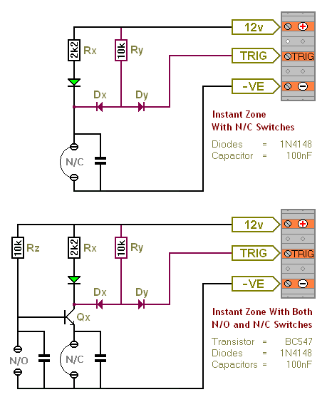
The Transistor Burglar Alarm System allows for the addition of multiple extra zones. The primary circuit is compatible with standard normally-closed input devices, including magnetic reed contacts, micro switches, foil tape, and passive infrared sensors (PIRs). An auxiliary circuit...

To achieve independence from local radio stations when testing VHF receivers, a frequency-modulated oscillator is required that operates within the range of 89.5 to 108 MHz. However, constructing such an oscillator using discrete components can be quite challenging. Maxim...
A 200-watt class-E AM transmitter designed for non-sanctioned broadcasting at a frequency of 1710 kHz. The schematic includes a negative peak limiter, an over-modulation indicator, a linear scale directional wattmeter, as well as power supply and antenna circuits. The 200-watt...