
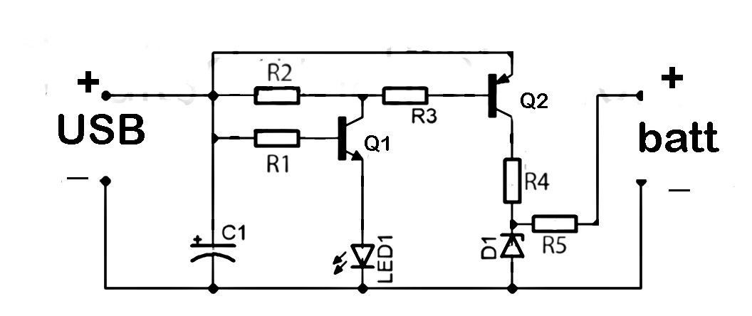
Schematic 1.3 Volt Power Source
The circuit employs a voltage regulation mechanism to convert the higher voltages from the PC power supply to the required 1.3V for the mercury cell replacement. The primary components of the circuit include a voltage regulator, capacitors for smoothing, and possibly a diode for reverse polarity protection.
The voltage regulator can be a low-dropout (LDO) type, which allows for efficient conversion of the 5V or 12V input down to 1.3V. The selection of the voltage regulator should consider the maximum current requirement of the load connected to the circuit, ensuring that it can supply sufficient current without overheating.
Capacitors are used in the circuit to filter out noise and stabilize the voltage output. Placing a capacitor at the input of the voltage regulator can help to smooth out any fluctuations in the power supply, while an output capacitor can enhance transient response and stability.
The inline fuse is an essential safety feature, protecting the circuit and connected components from potential overcurrent situations. A 100mA rating is appropriate for this application, as it allows for sufficient current flow while providing a safeguard against short circuits.
In summary, this circuit diagram serves as a practical solution for replacing small batteries in various applications, particularly in computers, by utilizing an efficient power conversion method and incorporating safety measures to ensure reliable operation.This circuit is a circuit diagram of resource replacement 1.3V mercury cells or other small batteries. This has many uses and you can use this circuit in the computer to turn on a front panel multi adapter which has a digital thermometer.
This circuit took power from the PC. Power connector cable has a color code, red and black is 12V supply, black and yellow is the 5V supply. This is now so high that the absolute care must be taken to avoid short circuit and inline fuse of 100mA is recommended
🔗 External reference
Related Circuits
A low power FM pirate radio. The output power is approximately +35 dBm (3.16 watts) over a 50-ohm load and operates on a +24-volt power supply. The project consists of a Hartley oscillator (modulated VCO) and three stages (Class...
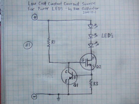
Here is a simple and cost-effective Power LED driver circuit. This power LED driver circuit is designed to efficiently drive high-power LEDs with a stable output. The circuit typically consists of a few key components: a power supply, a current...
Low-pass and high-pass audio output signal filters are included. An additional sound source low-pass filter and an experimental original design pulse-gate signal filter ("processor") are available, both featuring independent or linked voltage control input options. The synthesizer can function...
This document discusses the series used in USB connections for charging batteries. The output voltage ranges from 4.7 volts to 5 volts DC, which is suitable for charging mobile phones and other battery types. The circuit described enhances the...
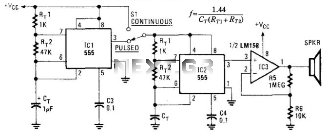
This circuit utilizes two NE555 timer IC devices to generate either pulsed or continuous ultrasonic signals. The values of CT for both pulse rate and ultrasonic frequencies can be calculated accordingly. SPKR refers to a small hi-fi tweeter. The circuit...
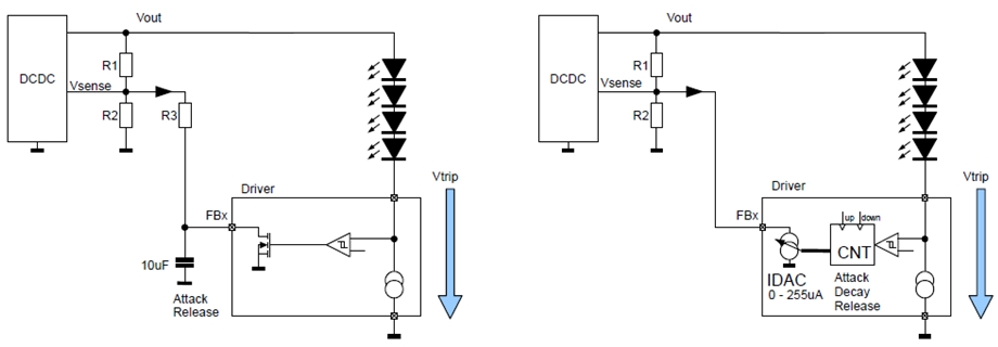
New design techniques in LED driver circuits promise to deliver significant energy savings that will help TV manufacturers meet stringent power consumption requirements. The advancement of LED driver circuits through innovative design techniques has the potential to yield substantial energy...
Warning: include(partials/cookie-banner.php): Failed to open stream: Permission denied in /var/www/html/nextgr/view-circuit.php on line 713
Warning: include(): Failed opening 'partials/cookie-banner.php' for inclusion (include_path='.:/usr/share/php') in /var/www/html/nextgr/view-circuit.php on line 713