
schematic 1 3 volt power source
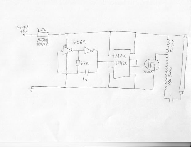
The circuit is designed to replace traditional 3V batteries with a more sustainable power source derived from a personal computer's power supply. This approach not only enhances the longevity of the device but also reduces the need for frequent battery replacements. The schematic shows the connections between the power supply and the multi-adapter, clearly indicating the appropriate voltage levels for optimal operation.
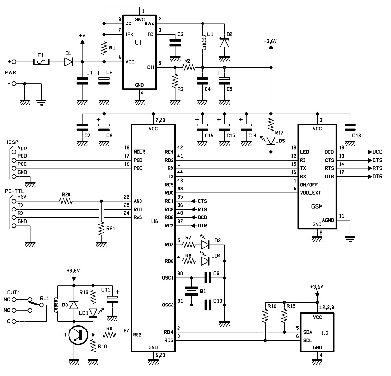
The red wire serves as the positive terminal for the 12V supply, while the black wire acts as the ground. The yellow wire indicates the 5V supply, which is essential for powering low-voltage components like the digital thermometer. The circuit must be carefully constructed to ensure that the voltage ratings are adhered to and that the components are compatible with the respective power supplies.
To prevent damage from potential short circuits, the inclusion of a 100mA inline fuse is crucial. This fuse will blow in the event of an overcurrent situation, thereby protecting the circuit and the connected components from damage. Proper insulation and secure connections should be maintained throughout the assembly to minimize risks associated with electrical faults.
In summary, this circuit diagram provides a reliable method for utilizing a PC's power supply to operate devices that typically rely on small batteries, enhancing both functionality and sustainability in electronic applications.This circuit is a circuit diagram of resource replacement 1. 3V mercury cells or other small batteries. This has many uses and you can use this circuit in the computer to turn on a front panel multi adapter which has a digital thermometer. This circuit took power from the PC. Power connector cable has a color code, red and black is 12V supply, blac k and yellow is the 5V supply. This is now so high that the absolute care must be taken to avoid short circuit and inline fuse of 100mA is recommended. The following is a schematic drawing: 🔗 External reference
Related Circuits
This circuit is an adjustable voltage reference circuit, which serves as a voltage source that provides a voltage greater than that of the reference diode. High precision applications that operate over an extended temperature range necessitate a restriction on...
The output current of the LM317T can be increased by incorporating an additional power transistor to share part of the total current. The current sharing is determined by a resistor connected in series with the input of the LM317...
The lighting hood of the AquaOne AR-320 tank typically comes with low-quality tubes that have inadequate power output and a color spectrum conducive to algae growth. Various improvement methods exist, such as replacing the hood with a metal halide...
The circuit is a comparator that measures the voltage of a car battery in steps of 1 Volt. The voltage measurement is performed by comparing the battery voltage, applied to the inverting inputs of amplifiers, against reference voltages produced...
Power is supplied by continuous voltage, which is not always stabilized, applied to PWR + and - at a value between 5 and 32V. This voltage is filtered at the bottom by a diode (D1) that protects against polarity...

The SPC2 is a solar power center, it can be used to handle all of the power functions for small 12 Volt solar powered devices. It contains a photovoltaic charge controller and a low voltage load disconnect circuit. The...