
LM317T Voltage Regulator with Pass Transistor
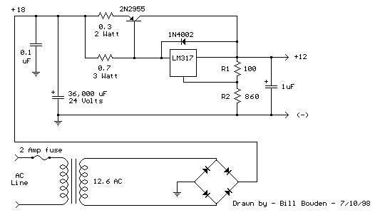
To design a circuit utilizing the LM317T for increased output current, it is essential to integrate a power transistor, typically an NPN type, which will serve as the pass transistor. The configuration involves connecting the collector of the NPN transistor to the output of the LM317T and the emitter to the load. The resistor in series with the LM317T input should be chosen to limit the current and ensure the safe operation of the LM317T, while the emitter resistor should be calibrated to facilitate proper current sharing between the LM317T and the power transistor.
The heat dissipation characteristics of the circuit necessitate careful thermal management. The LM317T and the pass transistor should be mounted on heat sinks capable of dissipating at least 23 watts to prevent thermal overload. The selection of the heat sink will depend on the ambient temperature and the thermal resistance of the heat sink material.
For the filter capacitor, the selection of a 36,000 µF capacitor is crucial for maintaining stable output voltage and minimizing ripple at full load. The capacitor must be rated for a voltage higher than the peak input voltage to ensure reliability. The power transformer should be rated to handle the required output current, with a secondary voltage that provides adequate headroom above the output voltage to account for the voltage drops across the regulator and series resistors.
The circuit design should also include appropriate protection features, such as fuses or circuit breakers, to safeguard against overcurrent conditions. Additionally, bypass capacitors may be included at the input and output of the LM317T to filter high-frequency noise and improve transient response. The overall design must adhere to best practices in PCB layout to minimize inductance and resistance in the power paths, ensuring stable operation under varying load conditions.The LM317T output current can be increased by using an additional power transistor to share a portion of the total current. The amount of current sharing is established with a resistor placed in series with the 317 input and a resistor placed in series with the emitter of the pass transistor.
In the figure below, the pass transistor will start con ducting when the LM317 current reaches about 1 amp, due to the voltage drop across the 0. 7 ohm resistor. Current limiting occurs at about 2 amps for the LM317 which will drop about 1. 4 volts across the 0. 7 ohm resistor and produce a 700 millivolt drop across the 0. 3 ohm emitter resistor. Thus the total current is limited to about 2+ (. 7/. 3) = 4. 3 amps. The input voltage will need to be about 5. 5 volts greater than the output at full load and heat dissipation at full load would be about 23 watts, so a fairly large heat sink may be needed for both the regulator and pass transistor. The filter capacitor size can be approximated from C=IT/E where I is the current, T is the half cycle time (8.
33 mS at 60 Hertz), and E is the fall in voltage that will occur during one half cycle. To keep the ripple voltage below 1 volt at 4. 3 amps, a 36, 000 uF or greater filter capacitor is needed. The power transformer should be large enough so that the peak input voltage to the regulator remains 5. 5 volts above the output at full load, or 17. 5 volts for a 12 volt output. This allows for a 3 volt drop across the regulator, plus a 1. 5 volt drop across the series resistor (0. 7 ohm), and 1 volt of ripple produced by the filter capacitor. A larger filter capacitor will reduce the input requirements, but not much. 🔗 External reference
Related Circuits

A voltage-controlled oscillator (VCO) operates similarly to a voltage-to-frequency converter (VFC). Its output frequency is determined by a control voltage input. In the circuit diagram, 'd' represents the amplifier input voltage, which is set to 0.6V, while 'h' denotes...
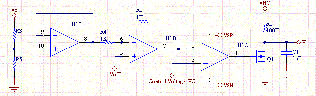
This circuit enables a smaller control voltage to inversely and linearly control a larger output voltage (Vo). Additionally, the supply voltage (Vsp) for the operational amplifiers can be lower than the output voltage, allowing the circuit to theoretically control...
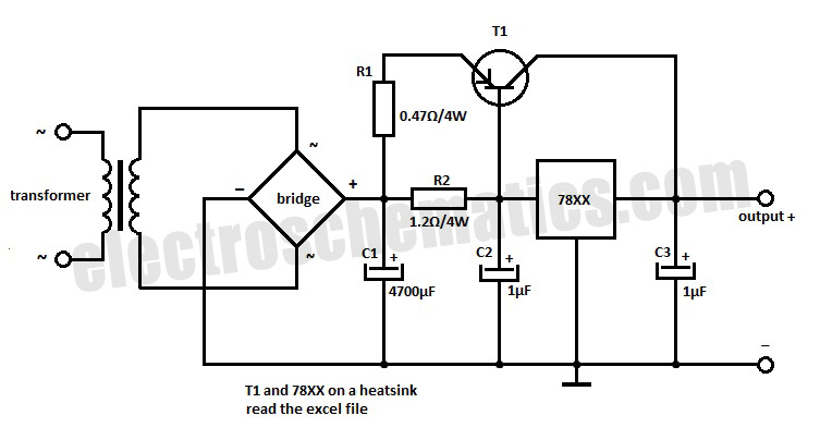
This voltage regulator extension circuit allows for an increase in output current up to 10 A. The T1 power transistor is configured with a resistor in the emitter. This voltage regulator extension circuit is designed to enhance the output current...
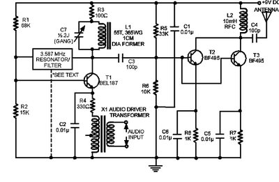
The circuit presented here is a powerful AM transmitter utilizing a ceramic resonator/filter operating at 3.587 MHz. This circuit primarily relies on a transistor for its core functionality. It is possible to use resonators/filters of other frequencies, such as...
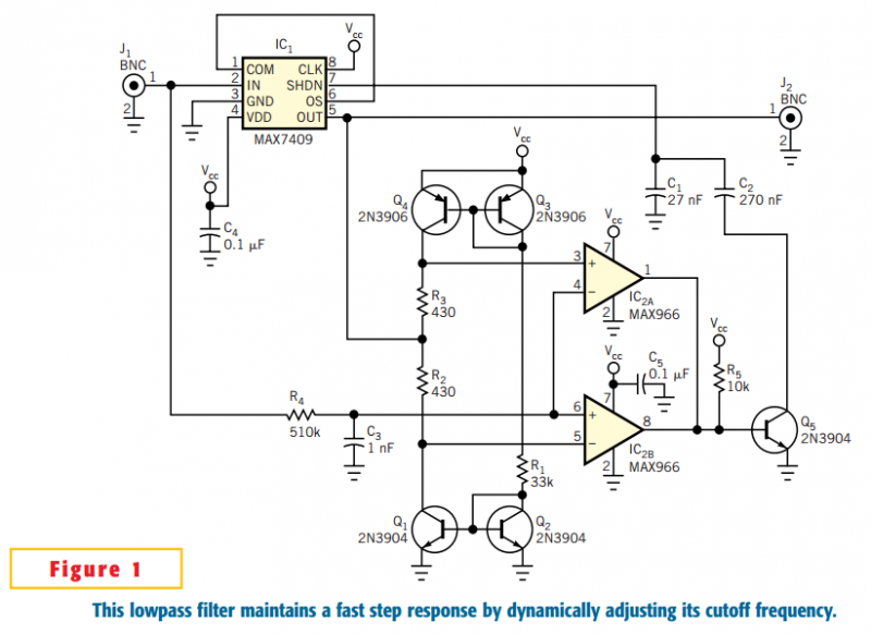
The circuit in Figure 1 accommodates lower cutoff frequencies without sacrificing the step-response time. A window comparator monitors the delta (difference) between the filter's input and output. When the delta exceeds ±50 mV, the filter increases its slew rate...
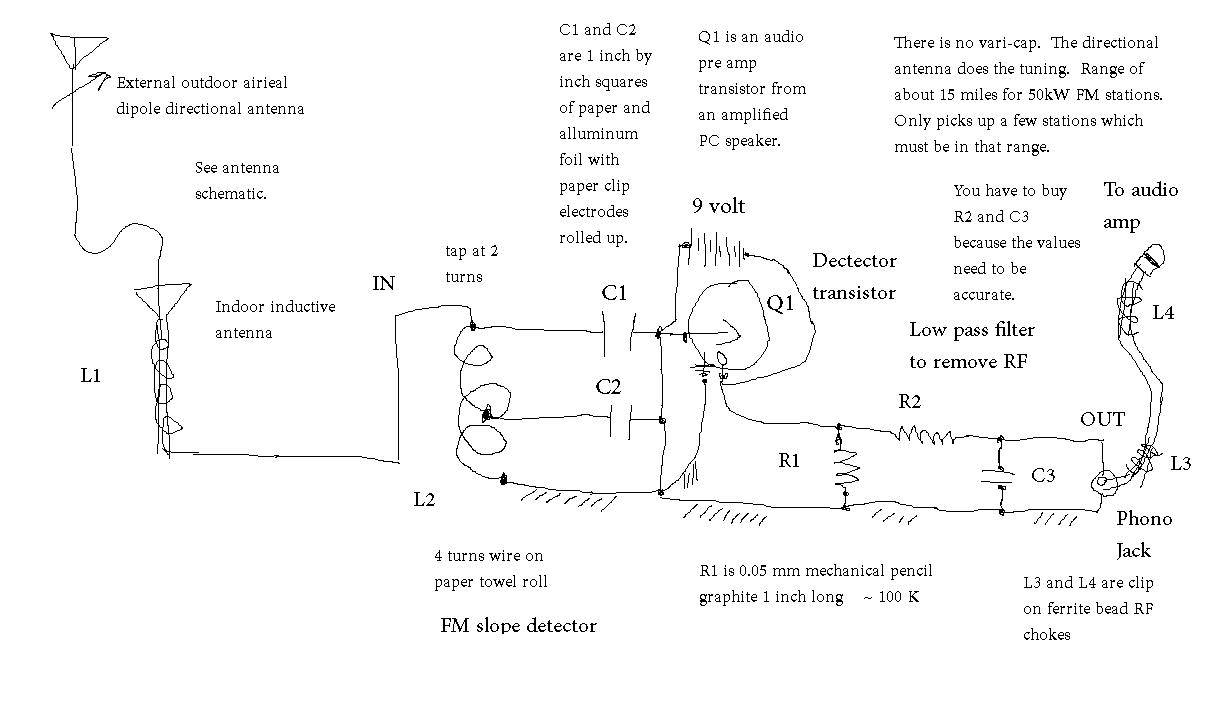
Seeking the appropriate resistor and capacitor values for a low-pass filter designed to eliminate radio frequency (RF) interference. The application focuses on filtering out unwanted untuned RF signals from a crystal radio set. A low-pass filter is an essential component...