
Time delay circuit (555)
The 555 timer in astable mode is widely utilized for generating square wave signals and timing applications. In this configuration, the 555 timer operates continuously, switching between its high and low states, thus creating a pulse output on pin 3. The frequency and duty cycle of the output waveform depend on the values of the resistors and capacitor connected to the timer.
In a typical setup, two resistors (R1 and R2) and one capacitor (C) are connected to the 555 timer. The output frequency (f) and the duty cycle (D) can be calculated using the following formulas:
- Frequency (f) = 1.44 / ((R1 + 2 * R2) * C)
- Duty Cycle (D) = (R2 / (R1 + 2 * R2)) * 100%
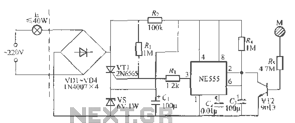
In this configuration, R1 is connected between VCC and pin 7 (discharge), while R2 connects pin 7 to pin 6 (threshold) and pin 2 (trigger). The capacitor C is connected from pin 6 to ground. To allow for adjustable timing, R1 can be replaced with a potentiometer, enabling the user to vary the resistance and thus alter the timing interval effectively.
The capacitor C must be selected based on the desired timing characteristics. It is essential to calculate its value using online 555 timer calculators, which can provide precise values based on the chosen resistances and the required frequency.
While this design is straightforward and effective for many applications, it may lack precision due to component tolerances and temperature variations. Nevertheless, its simplicity and ease of implementation make it a popular choice for triggering alarms, LED flashers, and other timing-related tasks in everyday electronics.
The output from pin 3 can drive various loads directly or via a transistor for higher current applications, making this configuration versatile for different electronic projects.A very regular configuration of the 555 astable timer to work as a timer to trigger an alarm or any other equipment connected to pin 3. R resistor should be replaced with a potentiometer that will change the time delay. Capacitor C should be calculated too (there are many 555 calculators around internet).Is a common design, not very accurate but very usefull in many everyday aplications.
🔗 External reference
Related Circuits
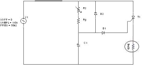
The diagram illustrates an R-C-Diode circuit that provides full half-cycle control (180 electrical degrees). During the positive half-cycle of the SCR anode voltage, the capacitor charges to the trigger point of the SCR, a process governed by the RC...
As with any audio mixer circuit, a slight loss is always introduced. The final summing amplifier has a gain of 2 or 6dB to overcome this. The input line level should be around 200mV RMS. The mic inputs are...
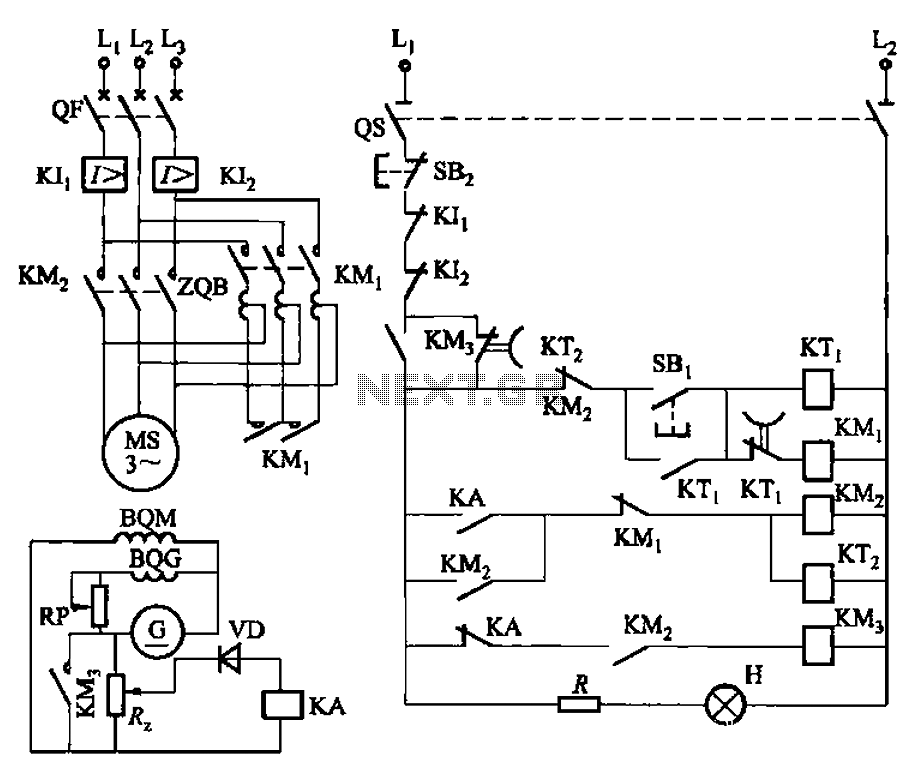
The circuit depicted in Figure 3-187 illustrates the operation of an auto step-down transformer (ZQB). Upon activation, the ZQB transformer initiates a sequence that allows the motor to gradually increase its speed. After a predetermined delay, the ZQB ceases...
Using a wire connection, utilize the NFA.55 timebase circuit delay type light touch switch, which can directly replace an ordinary mechanical switch without needing to modify the original internal wiring. The circuit is powered back with good hoof Chapter...
This circuit is an RMS-calibrated AC voltmeter that provides average readings. Removing capacitor C2 eliminates the averaging function, resulting in a precision full-wave rectifier, while removing capacitor C1 transforms the circuit into an absolute value generator. The operation of...
Top octave generators are known for being economical and compact compared to other tone generation methods. However, their near-perfect tuning often leads to chords that sound flat, particularly in organs where certain stops may not enhance the overall sound....
Warning: include(partials/cookie-banner.php): Failed to open stream: Permission denied in /var/www/html/nextgr/view-circuit.php on line 713
Warning: include(): Failed opening 'partials/cookie-banner.php' for inclusion (include_path='.:/usr/share/php') in /var/www/html/nextgr/view-circuit.php on line 713