
schematic of lenovo e317
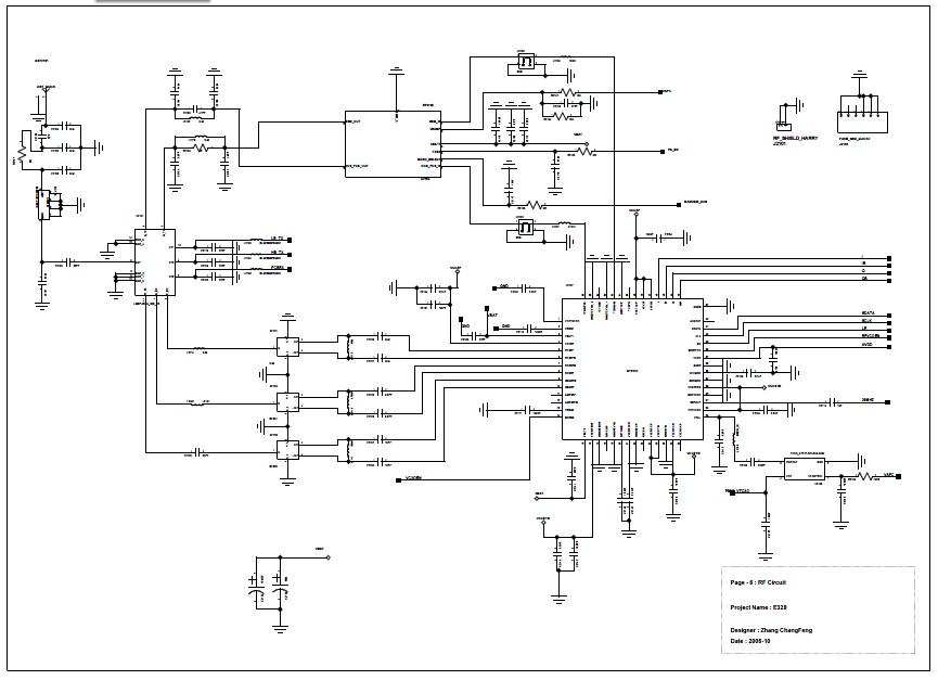
The analog baseband digital circuit encompasses a variety of interfaces and components essential for the operation of modern electronic systems. The EMI (Electromagnetic Interference) interface is crucial for ensuring that the circuit operates without interference from external electromagnetic sources, thereby maintaining signal integrity. The BPI (Bus Protocol Interface) bus facilitates communication between different components, allowing for efficient data transfer and control signals.
The JTAG (Joint Test Action Group) interface is employed for testing and debugging purposes, enabling access to the internal states of the circuit and providing a means to program devices. The LCD (Liquid Crystal Display) interface allows for visual output, while the keypad interface enables user input, both of which are vital for user interaction with the device.
UART (Universal Asynchronous Receiver-Transmitter) is a standard communication protocol used for asynchronous serial communication, providing a reliable method for data exchange. The MINT (Microcontroller Interface) and GPIO (General Purpose Input/Output) pins offer additional flexibility in interfacing with various peripherals.
The MCP (Microchip Technology) keypad is utilized for enhanced user input capabilities, and audio components are integrated for sound processing. RF (Radio Frequency) elements are included for wireless communication, while I/O connectors provide physical connections to external devices.
Power management is addressed through power cones, which regulate voltage levels, and the battery charging circuit ensures efficient power supply management. The analog LED driver controls the brightness of LEDs, and RF control circuitry manages radio frequency signals. The IOTA (Input/Output Asynchronous Transfer Architecture) enhances data handling capabilities.
Audio codecs are incorporated for digital audio processing, enabling high-quality sound reproduction. The MCU (Microcontroller Unit) serves as the central processing unit, coordinating all operations within the circuit. SIM level shifters are essential for interfacing with different voltage levels, ensuring compatibility with various components. Finally, voltage regulators maintain stable power supply levels for the entire circuit, ensuring reliable operation across all components.Analog baseband digital circuit table of contents:, Emi interface, BPI bus, Jtag, LCD interface, keypad, UART, mint, Gpio, and Mcp keypad, audio, RF, I/O connectorPower cones, serial time, battery charging and analog, Led driver, RF control, Jtag, iota, audio codecs, MCU, SIM level shifters, voltage regulator 🔗 External reference
Related Circuits
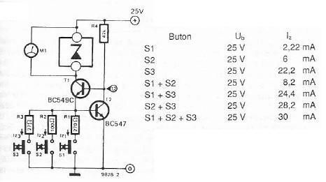
The electronic scheme provided can be used to design a Zener diode tester utilizing a few electronic components. This Zener tester, in conjunction with a multimeter, allows for the precise measurement of the threshold voltage of a Zener diode....
According to the note on the schematic, IC-2 is a 74HC74 TTL chip. Refer to the data sheet for details regarding pins 7 and 14. The note for IC-3, located lower on the schematic, indicates it is an AC...
There are at least three different versions of this circuit. The first DM-2 version utilized the MN3005 BBD and the MN3101 Clock Driver IC (PCB marking: ET5214-510). Later, the clock driver was changed to the MN3102, and the BBD...
This is a simple scheme for a bridge oscillator. It provides a nice sinusoidal signal. This type of oscillator uses an op-amp. The weakening of the oscillating member (R1, R2, C1, C2) is 3x. To compensate, the attenuated signal...
The objective is to enhance information transmission by utilizing articles. Please contact us via email at [email protected] within 15 days if there are issues related to article content, copyright, or other concerns. Prompt action will be taken to resolve...
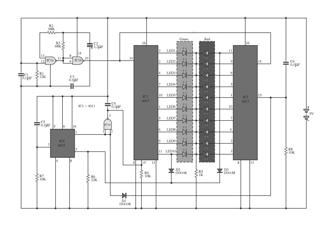
This circuit operates on alternating two colors using a 2-color LED with a built-in 3-pin configuration. It alternates the glow of each LED until the base, switching between two colors. The circuit comprises a NAND gate IC, two 10-counter...