
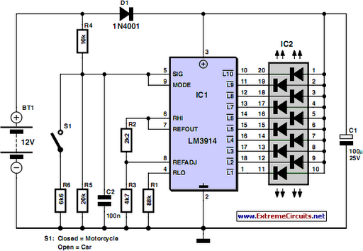
zener diode tester schematic

The Zener diode tester circuit comprises several essential components, including resistors, transistors, and switches, which work together to facilitate accurate measurements of the Zener diode's breakdown voltage. The core of the circuit is the Zener diode, which is connected in parallel with a voltmeter to enable direct voltage readings. When switch S1 is closed, current flows through the circuit, allowing the Zener diode to operate in its breakdown region.
Transistor T1 plays a crucial role in the circuit by regulating the current through the Zener diode. The base of T1 receives voltage from the power supply through resistor R4, which ensures that T1 remains in the 'on' state, allowing current to flow. The current through the Zener diode is influenced by the base-emitter voltage of transistor Q2, which is in turn affected by the value of resistor R1. This relationship allows for precise control of the Zener current, making it possible to measure different current levels accurately.
The circuit is designed to operate with a supply voltage of 25 volts, and by adjusting the configuration of resistors R1, R2, and R3 through switches S2 and S3, the current through the Zener diode can be varied. This adaptability enables the tester to measure Zener diodes with different specifications and characteristics. The ability to switch between different resistor combinations allows for a constant current to flow through the Zener diode, ensuring that the voltage readings obtained are stable and reliable.
Overall, this Zener diode tester circuit is a practical tool for electronics enthusiasts and professionals, providing a straightforward method for evaluating the performance of Zener diodes in various applications.Using electronic scheme below can be designed a zener diode tester using few electronic parts. Using this zener tester and a multimeter can be measured and determined with a high precision threshold voltage of a zener diode. Zener voltage can be read with a DC voltmeter connected in parallel with zener diode. If contact S1 is closed, the resistance R1, T1 and Zener diode current flow. Base transistor T1 is connected to power supply trough the R4, so the transistor conducts. Zener current is equal to the ratio of base-emitter voltage of Q2 and the resistance value R1. With a supply voltage of 25 volts at the actuation keys S1-S3, the current through zener diode take values of about 2. 2, 6 and 22mA. Resistances R2 and R3 or a combination of R1, R2, R3 can be connected in place of R1 with S2-S3 so that through the zener diode constant current flow.
🔗 External reference
Related Circuits
Camping today often requires various electronic devices for daily activities and entertainment. Typically, a charged lead-acid battery and a power inverter are utilized to ensure a well-organized trip, allowing family members to enjoy their electronic equipment. It is essential...
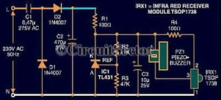
An infrared remote control tester circuit that can be constructed inexpensively. This IR tester is built around an infrared receiver module TSOP1738. The remote control's state can be observed through the sound of a buzzer. The circuit is highly...
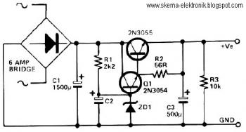
This circuit can be utilized in applications requiring high current and low ripple voltage, such as in high-powered Class AB amplifiers where high-quality audio reproduction is essential. Q1 and Q2, along with resistor R2, function as a power Darlington...
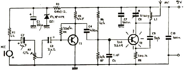
This FM transmitter electronic project operates in the FM band with a transmission power of approximately 250 mW. The circuit is straightforward and utilizes common transistors and electronic components. The T1 transistor, which may be a BC107, BC171, or...
This circuit utilizes the TLC555CP timer integrated circuit to flash an LED approximately twice per second. This specific 555 timer operates on a voltage of only 3 volts, allowing it to be powered by two 1.5-volt cells. When using...
A bandpass filter passes a range of frequencies while rejecting frequencies outside the upper and lower limits of the passband. The range of frequencies to be passed is called the passband and extends from a point below the center...