
schematics Control speed of Nidec fan

To achieve variable speed control for the Nidec TA450DC fan, a pulse-width modulation (PWM) controller can be employed. This method allows for effective speed regulation while maintaining low noise levels. The fan operates on a 12V DC supply, and the red wire is connected to the positive terminal, while the black wire connects to ground. The blue and yellow wires typically serve as a tachometer output and a PWM control input, respectively.
A suitable approach involves using a PWM speed controller circuit, which can be constructed using a transistor or a dedicated PWM controller IC. The PWM signal modulates the voltage supplied to the fan, effectively controlling its speed. The circuit can be designed with a potentiometer (variable resistor) that acts as the speed control knob. The potentiometer is connected in such a way that it adjusts the duty cycle of the PWM signal based on its position.
The wiring configuration would include connecting the potentiometer to the control input (yellow wire) of the fan. The PWM circuit's output will be fed into the yellow wire, while the blue wire can be left unconnected if it is solely for tachometer feedback, which may not be necessary for basic speed control.
For assembly, a small circuit board can be used to house the components. The PWM circuit will require a power source, which can be derived from the same 12V supply used to power the fan. The transistor or PWM controller IC can be mounted on the board, with the potentiometer accessible from the exterior for user adjustment.
In summary, the desired outcome is to create a simple yet effective PWM speed control circuit that utilizes a potentiometer to adjust the fan speed smoothly from minimum to maximum, while ensuring that the fan operates quietly and efficiently within the wooden cabinet.I have a Nidec TA450DC B35502-35 fan which I`ve installed in a large wooden cabinet where my computer and other electronics sit. This cabinet of course gets hot from all the electronics inside of it. The fan forces air in from the room and goes out through openings in the top of the cabinet. This fan has 4 wires: red (+12v), black (ground), and then blue and yellow. I`m using only red and black to give the fan full 12v power. The problem is since it`s at max speed, it is way too loud. I have a simple toggle switch to turn it on and off. What I would like to do is replace the toggle switch with a knob to adjust the speed. I don`t know how to use the other two wires to control the speed. What kind of knob do I need to get, and how should I wire it The minimum setting of the knob should feed the fan with its minimum required power to spin at the lowest speed possible, and the highest setting should spin it at full possible speed. I don`t have any problem with soldering a small circuit board together for this project, I just have no idea what schematic I need to put together.
I`ve played with electronics and their components all my life but don`t know nearly enough to even begin understanding how to accomplish this. It should be simple, right Should I be using one or both of the additional wires for this, or should I use some method of adjusting the voltage
🔗 External reference
Related Circuits
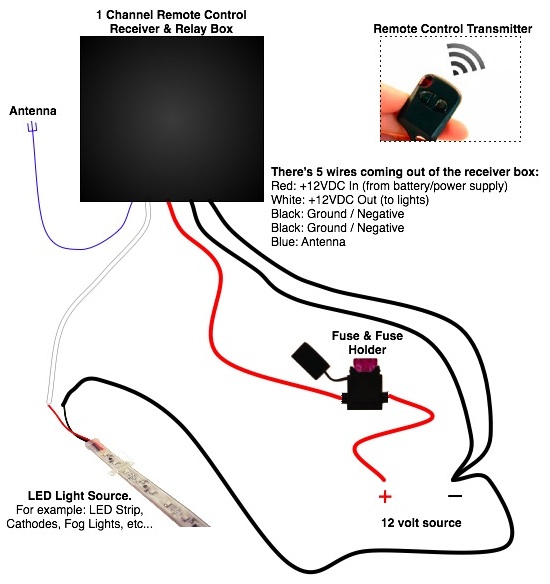
Installing a small dash-mounted two-speed fan in a motorhome. What is the best method? Use a one-channel relay or a four-channel relay with separate wires (one for low speed and one for high speed)? Any additional ideas? Would it...
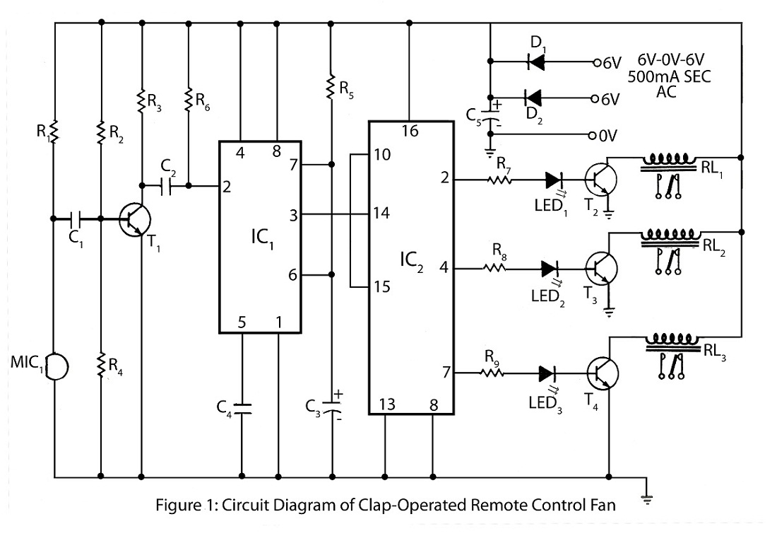
The clap-operated remote control for fans is designed to control a ten-step speed fan circuit. This includes a circuit diagram and a description of the clap-operated remote control system for fans. The clap-operated remote control system utilizes sound recognition to...
This is a TV remote control jammer circuit. Remote controls use modulated light to combat interference from background infrared noise. Your room heater, etc. The TV remote control jammer circuit is designed to disrupt the operation of infrared remote controls...
Introduction The ignition timing lights commonly used range from simple neon to complex units. Neon timing lights have a drawback due to their low light output, necessitating operation in subdued lighting. This presents a safety hazard, as users tend...
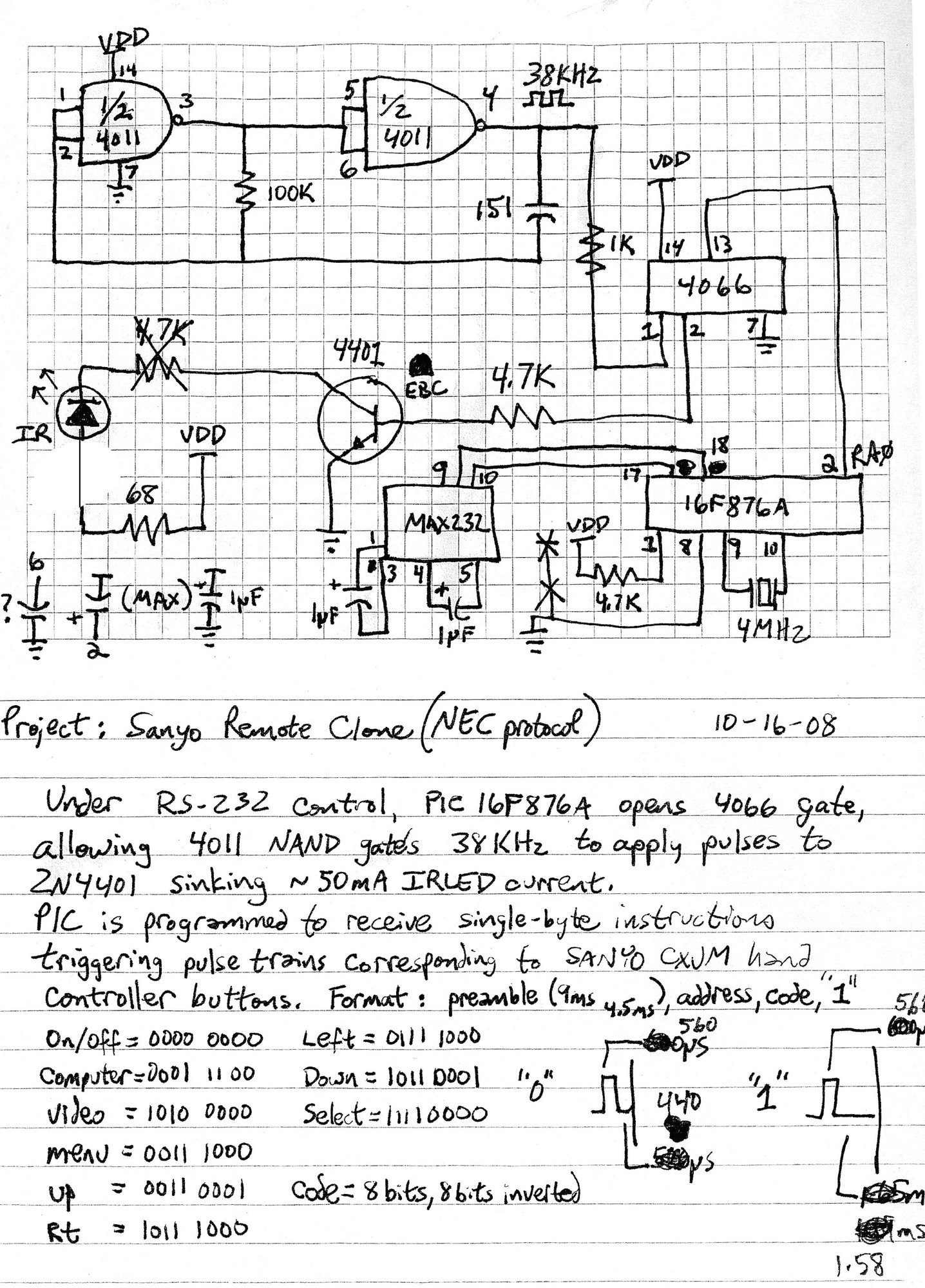
Electronics Nerd demonstrates the process of reverse engineering an infrared (IR) remote control signal. By understanding the type of signal transmitted by the remote, a microcontroller can be programmed to simulate the code necessary to control the Hampton Bay...
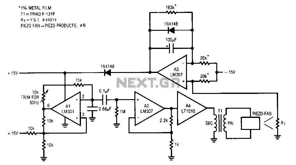
The fan used is a new electrostatic type, known for its reliability due to the absence of wearing parts. These devices require a high-voltage drive. When power is applied, the thermistor located in the fan's exhaust stream has a...