
tv remote control jammer
The TV remote control jammer circuit is designed to disrupt the operation of infrared remote controls by emitting modulated infrared signals that interfere with the signals sent from the remote control to the television. This circuit typically consists of an infrared LED, a modulation circuit, and a power supply.
The infrared LED serves as the primary emitter of the jamming signal. It is driven by a modulation circuit that generates a pulsed signal at a frequency similar to that of standard remote control devices, which typically operate in the range of 30 kHz to 40 kHz. This modulation is crucial as it allows the jammer to effectively mask the signals emitted by legitimate remote controls.
The power supply for the circuit can be a simple battery or a regulated power source, depending on the design requirements. It is essential to ensure that the power supply provides sufficient current to the infrared LED for effective jamming without overheating or damaging the components.
In terms of layout, the circuit should be designed to minimize interference with other electronic devices and should incorporate proper shielding to prevent unintended emissions. The use of a microcontroller can enhance the functionality of the jammer by allowing for adjustable modulation frequencies and the ability to turn the jamming signal on and off as needed.
Safety and legal considerations must be taken into account when using or building a remote control jammer, as jamming signals can interfere with legitimate communications and may be regulated or prohibited in certain jurisdictions.This is a TV Remote Control Jammer circuit. Remote control use modulated light to combat eer infrared nvironment/background infrared noise. Your room heater,.. 🔗 External reference
Related Circuits
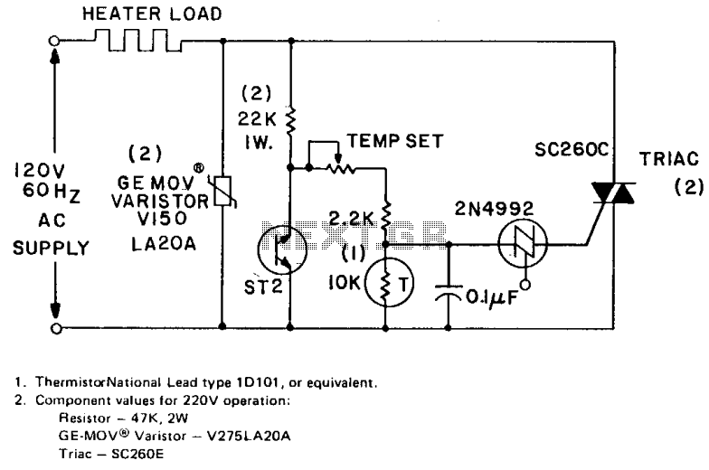
The circuit can control up to 6 kW of heating with moderate gain using a 25-amp triac (SC260D). Feedback is provided by a negative temperature coefficient (NTC) thermistor, which is positioned near the environment being temperature controlled. The temperature...
This project describes a new economical solution of home light control systems. The presented home light control system can be used for different sophisticated home applications. The control system consists of a PC, and control circuitry and the electrical...
Electric motors have been widely used for motion control, and various types of motor controllers have been designed to provide variable speed drives for these motors. Electric motors are integral to numerous applications requiring precise motion control, ranging from industrial...
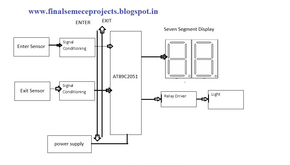
This project involves an automatic room light controller with a bidirectional visitor counter using a microcontroller. It is designed to manage room lighting and accurately count the number of individuals present. When a person enters the room, the counter...
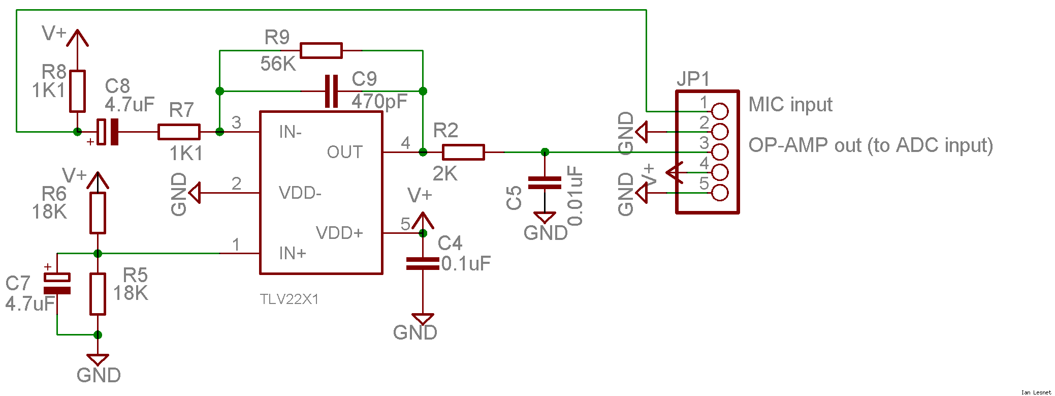
This project utilizes a small, common electret microphone to convert audio into an electrical signal. These inexpensive microphones are typically found in most PC headsets. The output from the microphone must be amplified and zeroed before it can be...
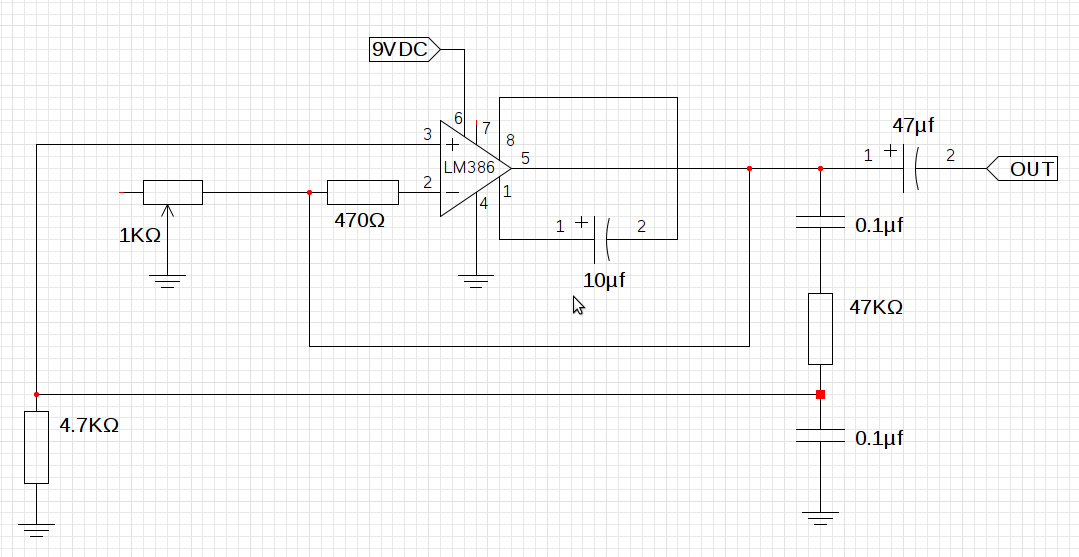
The design utilizes the LM386n-1 integrated circuit, powered by a single power supply to maintain a compact layout. There is a need to control the frequency, and the user is inquiring about which component values should be adjusted for...