
schematics electronic telephone ringer
The circuit functions as a multi-tone generator, utilizing three oscillators to create a complex audio output. The first oscillator, designed to operate at a low frequency, serves as a trigger for the subsequent oscillators, ensuring a sequential activation that contributes to the overall sound modulation. The second oscillator introduces a modulation effect that enhances the auditory experience by varying the tone slightly, while the third oscillator generates the primary frequency that is perceived as the ringing sound.
Each oscillator's frequency is finely tuned using the associated resistors and capacitors, allowing for precise control over the output sound characteristics. The use of operational amplifiers in conjunction with feedback resistors ensures that the oscillators maintain stability and produce consistent waveforms. The piezo sounder, a crucial component in the circuit, effectively converts the electrical oscillations into sound waves, providing the audible ringing effect.
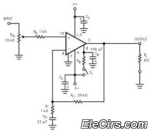
Power supply considerations are also critical, as the circuit operates efficiently within a specified voltage range. The current consumption is relatively low, making the circuit suitable for battery-powered applications. The design's simplicity and effectiveness in generating a ringing sound make it an excellent choice for various electronic projects requiring sound generation. Overall, this circuit exemplifies a well-structured approach to audio signal generation, combining multiple oscillators to achieve a desired auditory output.This circuit produces a ringing sound similar to that made by more recent telephones. It consists of three almost identical oscillators connected in a chain, each generating a squarewave signal. The frequency of each oscillator depends on the RC combination: R4 and C1 around IC1. A, R8 and C2 around IC1. B and R12 and C3 around IC3. C. The pairs of 1 00 k resistors divide the asymmetric power supply voltage (between 5 V and 30 V) so that, in conjunction with the 100 k feedback resistors (R3, R7 and R11) either one third or two thirds of the supply voltage will be present at the non-inverting inputs to the opamps. The voltage across the capacitor therefore oscillates in a triangle wave between these two values. The first oscillator is free-running at a frequency of approximately 1/3 Hz. Only when its output is high, and D1 stops conducting, can the second oscillator run. The frequency of the second oscillator is about 13 Hz, and optional LED D3 ¬‚ashes when it is running.
When the output of the second oscillator is low, the third is allowed to run. The frequency of the third oscillator is around 1 kHz, and this is the tone that is produced. The second oscillator is not absolutely necessary: its function is just to add a little modulation to the 1 kHz tone. A piezo sounder is connected to the output of the third oscillator to convert the electrical signal into an acoustic one.
The current consumption of the circuit is just under 1mA with a 5V power supply, rising to about 1. 65mA with a supply voltage of 15 V. 🔗 External reference
Related Circuits
Multi-spark ignition is very useful especially in the case of startings at low temperature and at low rpm range. Basic idea, is to apply to spark plugs instead of only one spark, a spark-burst having big energy. In this...
The Link circuitry is simple and efficient, employing just two integrated circuits (ICs), a few transistors, and common components. It operates on 12 volts and is easy to assemble. This intercom system can connect various locations such as the...
Electronic Project EPROM Emulator. This EPROM Emulator was designed to complement the EPROM Programmer (Mark 2). The EPROM Emulator serves as a versatile tool for testing and developing electronic circuits that utilize EPROM (Erasable Programmable Read-Only Memory) chips. This device...
This is a circuit for alternative sources selection. It combines mechanical selection using a rotating switch S1, the electronic drive of the relays RL 1-10 and also the optical indication of the selection by the Display DSP1. The function...
The LM3886 high-performance audio power amplifier circuit schematic is a crucial component in sound reproduction within audio systems. This audio power amplifier utilizes the LM3886 integrated circuit to enhance sound quality and output. The LM3886 is a high-performance audio power...
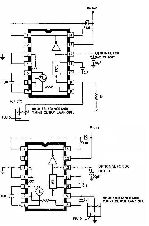
This electronic liquid detector circuit diagram is based on the ULN2429 monolithic bipolar integrated circuit designed for detecting the absence or presence of many different types of liquids. The ULN2429 electronic liquid detector circuit can be used in automotive,...