
ULN2429 liquid detector circuit diagram electronic project
The ULN2429 integrated circuit serves as a versatile solution for liquid detection across various environments. It operates by utilizing a probe that is immersed in the liquid being monitored. The resistance of the probe changes based on whether the probe is submerged in a liquid or exposed to air. This resistance change is compared to a predetermined internal or external reference resistance to determine the liquid's presence or absence.
The circuit can be configured to drive several types of output devices. When a liquid is detected, the output of the ULN2429 can activate an LED to provide a visual indication of the liquid's presence. Alternatively, it can drive an incandescent lamp for more substantial illumination or a loudspeaker for auditory alerts. The design also supports the operation of relays and solenoids, which can be used for automated control systems, such as shutting off a valve or activating a pump.
To ensure the output signal is suitable for these devices, a capacitor must be connected to pin 12 of the ULN2429. This capacitor smooths the output signal, converting the typically generated square wave into a more stable DC signal. This adjustment is critical when interfacing with devices that require a steady voltage supply.
For applications that necessitate higher voltage outputs, the ULN2429A-1 variant is recommended. This version of the integrated circuit retains the same functionality while accommodating devices that operate up to 50 volts, thereby expanding the range of potential applications in industrial settings where higher voltage systems are common.
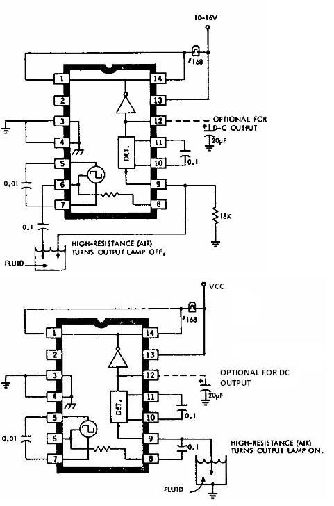
Overall, the ULN2429 liquid detector circuit is a robust and flexible design suitable for various liquid detection applications, providing reliable performance and ease of integration into existing systems.This electronic liquid detector circuit diagram is based on the ULN2429 monolithic bipolar integrated circuit designed for detecting the absence or presence of many different types of liquids. The ULN2429 electronic liquid detector circuit can be used in automotive, home or industrial applications.
The absence or presence of the liquid is deter mined by comparing the loaded probe resistance (probe immersed in the fluid ) with an internal or external resistance. At the output you can connect a LED, incandescence lamp, loud speaker or even such relays or solenoids, but just I you connect at pin 12 a capacitor, to provide a dc output ( typically the output signal is a square wave ).
If you need to connect at the output a device that need more than 30 volts you can use the ULN2429A-1 which is identical, but support devices with operation up to 50 volts. 🔗 External reference
Related Circuits
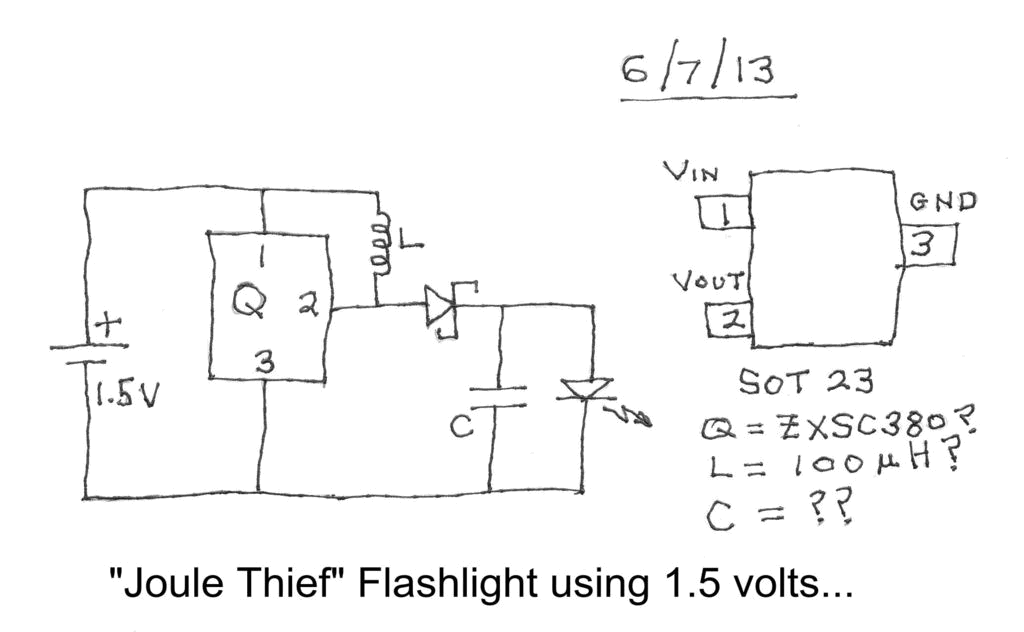
Investigating a Paradox: Recently, an energy-saving LED flashlight was observed for sale that utilized only one 1.5-volt battery. Upon purchasing this light and disassembling it, the expectation was to find a battery, bulb, switch, and a circuit board designed...
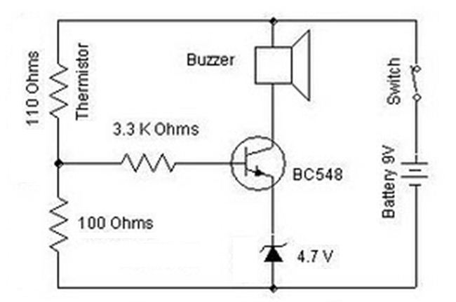
A heat sensor circuit can be utilized to control any device using a heat sensor. In this circuit, a thermistor and a resistor are connected in series, forming a potential divider circuit. The thermistor is of the Negative Temperature...
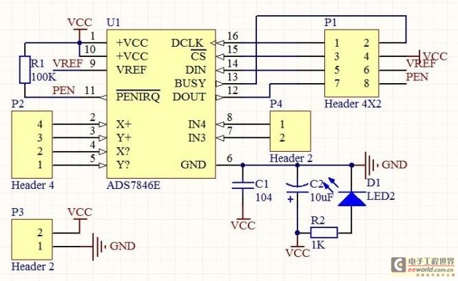
The touch control screen is a common feature in modern electronic products, typically incorporating a colored liquid crystal display (LCD) with a touch-sensitive interface. This technology is user-friendly and effectively replaces traditional fixed keypads. This document introduces the driving...

The circuit includes a K-type thermocouple cold junction compensation circuit, a precision 5.000V reference voltage source, and an OP113 operational amplifier. It is capable of measuring temperatures ranging from 0°C to 100°C with a resolution of 0.02°C. The OP113...
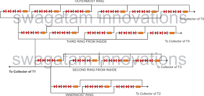
The following article outlines a sophisticated LED sequencing and diverging ring light that can serve as a tail brake light in vehicles. This circuit concept was proposed by a dedicated reader, Mr. Bobby. The design aims to create a...
This circuit diagram illustrates the design of a straightforward AC voltage converter that transforms 240V AC power into 110V AC. The circuit can effectively be utilized to power electrical devices that necessitate a supply voltage of 110V. The AC voltage...