
Electronic 10 way Selector Relays

The circuit is designed to facilitate the selection of alternative sources using both mechanical and electronic components. The mechanical selection is achieved through a rotary switch (S1), which allows the user to choose among ten different options. Each position of the switch corresponds to a unique state represented in Binary-Coded Decimal (BCD) format.
The electronic control of the relays (RL1 to RL10) is handled by a combination of diodes (D1 to D10) that ensure proper signal routing and isolation between different paths. The BCD input from the switch is processed by the IC2, which is a BCD to decimal decoder (CD4028). This IC translates the BCD input into a corresponding decimal output, activating the appropriate relay based on the selected input.
The display of the selected option is managed by IC1, a BCD to 7-segment latch/decoder/driver (CD4511). This component takes the BCD output from IC2 and drives a common cathode 7-segment display (DSP1), providing a visual representation of the selected source.
The circuit includes a variety of resistors (R1 to R12) and capacitors (C1, C2) that help in biasing and stabilizing the circuit. The relays (RL1 to RL10) can operate at either 6V or 12V, allowing for flexibility in power supply choices. Additionally, there is potential for further enhancements, such as adding LEDs in parallel with the relays to provide additional visual feedback for the selected options. This circuit design allows for versatile combinations and selections, making it suitable for various applications where source selection is required. This is a circuit for alternative sources selection. It combines mechanical selection using a rotating switch S1, the electronic drive of the relays RL 1-10 and also the optical indication of the selection by the Display DSP1. The function is based on the connection of the mechanical selections into 4 Bit (BCD) code. It is managed by the proper polarization of the diodes D1-10 and simultaneous convention into decimal output by IC2 which is a BCD to decimal decoder.
The monitor is driven by the IC1, which is a BCD to 7- segment Latch/ decoder/ driver. We can made a lot of combinations and selections on the circuit. For instance, we may add Led' s in parallel with the RL1-10. Code BCD to decimal converter for CMOS Part List R1....4= 10Kohms C2= 47uF 25V Q1-10= BD679 R5....11= 820 ohms D1.....20= 1N4148 DSP1= Display 7 segment Common Cathode R12....21= 15Kohms IC1= 4511 S1= 1X10 Step Selector C1= 100nF 63V MKT IC2= 4028 RL1....10= 6V or 12V Relay 🔗 External reference
Related Circuits
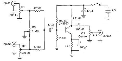
This audio mixer circuit diagram electronic project is designed using a few common electronic components. The audio mixer circuit project has two input channels. The input signal can be independently controlled using the R1 and R2 variable resistors. The...
Embedded systems serve as the core of most electronics-based systems, enabling data access, processing, storage, and control. While some simple electronic circuits can be designed without a microprocessor or microcontroller, this approach is often economically impractical, except for basic...
The alarm will switch off when the 4 keys connected to "A,B,C,D" are pushed in the right order. The circuit works because each gate stands upon its predecessor. If any key other than the correct key is pushed, then...
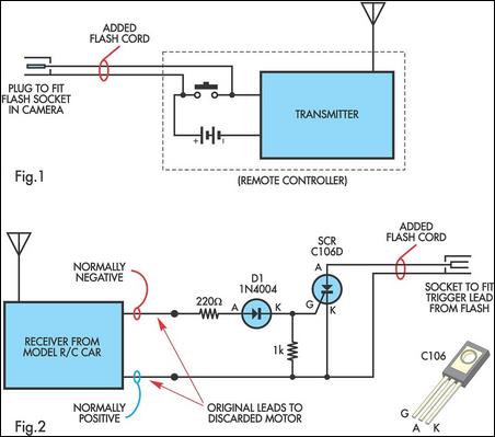
A radio-controlled electronic flash is a valuable tool in any photographer's kit, frequently utilized by professionals. For instance, a wedding photographer may position one behind the bride to illuminate her gown and veil, avoiding visible wires in the shot....
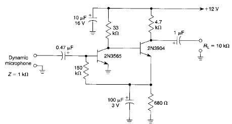
This microphone preamplifier electronic project is based on transistors and is capable of approximately 70 dB or more gain at audio frequencies. The gain of this circuit is roughly equal to the product of the hfe (current gain) of...
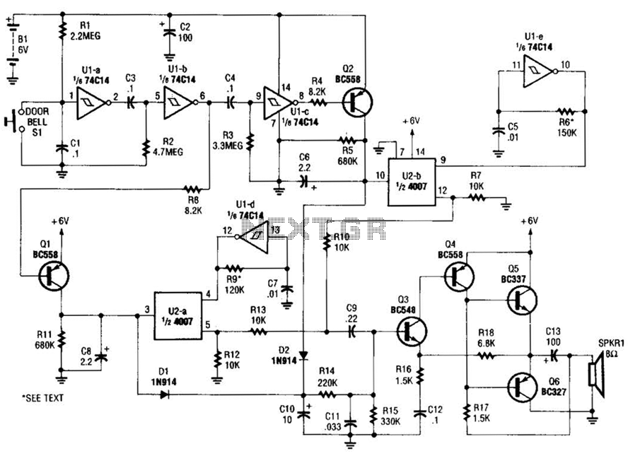
When the doorbell switch is pressed, two monostable stages are sequentially activated, applying bias to a pair of voltage-controlled resistor stages. These stages modulate the outputs from a pair of tone generators. The resulting signals are then fed to...