
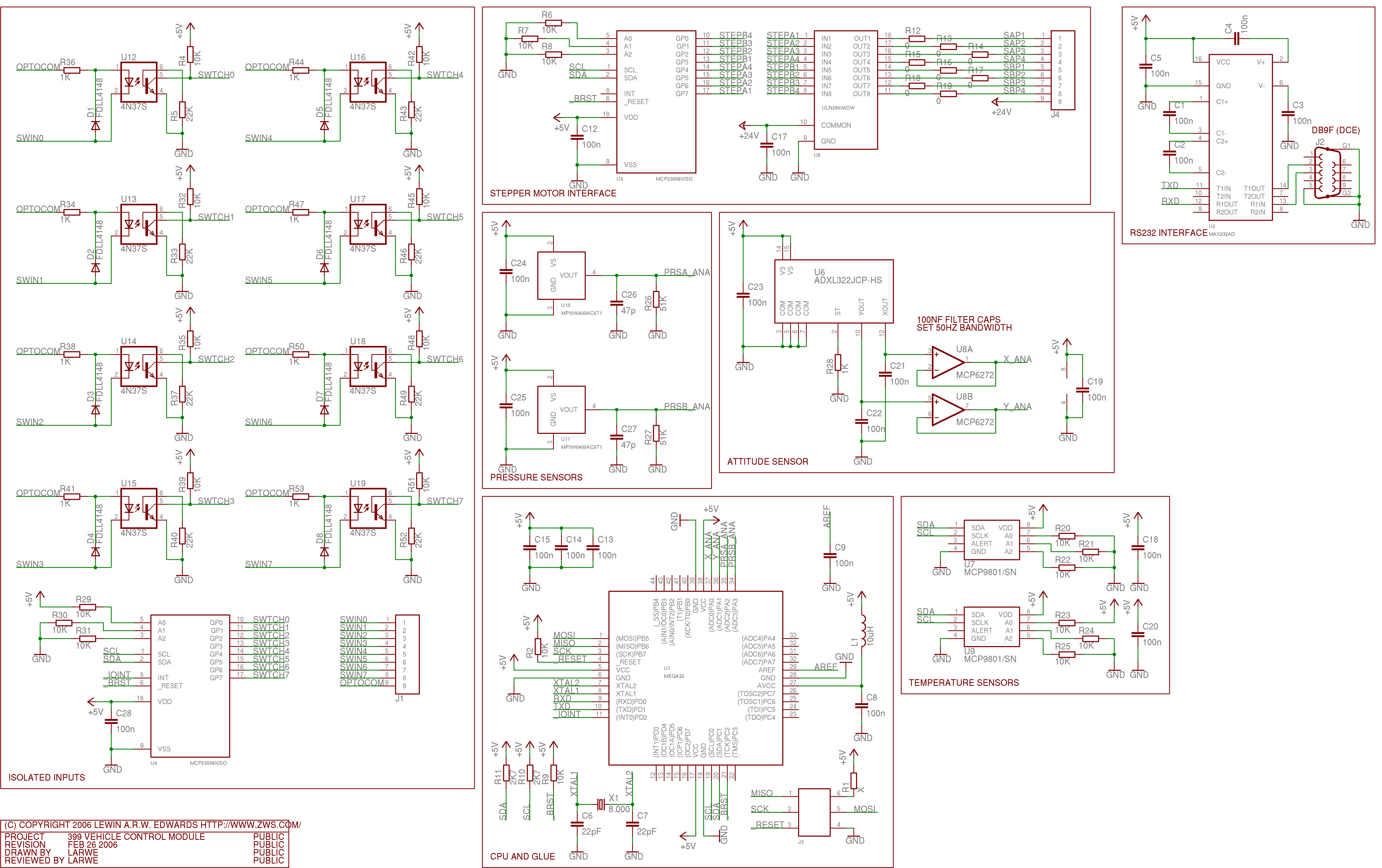
Schematics power supply switching PCB

The switching power supply described operates by converting input voltage to a regulated output voltage of 12 volts while ensuring a maximum current capacity of 10 amps. The use of a discrete transistor regulator in conjunction with an operational amplifier as a comparator is a critical aspect of the feedback mechanism, allowing for precise control of the output voltage. The absence of a front panel power-on light in the schematic may suggest a design focused on functionality without additional user interface elements.
The current limiting feature, while not adjustable, is effectively managed by the specified components, which work together to ensure that the output current does not exceed 10 amps. This limitation is crucial for protecting both the power supply and connected loads from overcurrent conditions. The addition of inductive component L1 and diode D1 indicates an effort to minimize voltage spikes and enhance the overall performance of the switching regulator.
The operational behavior of this power supply is characterized by its variable switching frequency, which adjusts in response to load changes. This characteristic can lead to inefficiencies and electromagnetic interference, making PWM regulators a more favorable choice in contemporary designs. PWM technology allows for a stable switching frequency, significantly reducing the potential for spurious emissions and improving overall efficiency.
The inclusion of a Darlington pair in the pass transistor stage provides high current gain and robustness, ensuring the power supply can handle the maximum load without significant thermal stress or degradation. The parallel configuration of the Darlington-connected transistors adds redundancy, further enhancing reliability during operation.
Finally, the internal trim-pot (R4) offers flexibility in output voltage adjustment, allowing the user to set the output anywhere between 5 to 15 volts. This feature makes the power supply versatile for various applications, accommodating different voltage requirements while maintaining stability and performance.The switching power supply provides 12 volts, at 10 amps, maximum, using a discrete transistor regulator with an op-amp functioning as a comparator in the feedback circuit. With reference to the schematic, the front panel power-on light is not shown. There is no adjustable current limiter in this unit, although R1, R2, R3, Q2, R8, R9, C5 and Q4 se t the current limit to approximately 10 amps. As you can see, the design is very similar to that of a linear power supply, except that L1, and D1 have been added, and U1 operates in a switching mode as a comparator with a small amount of hystersis. The switching frequency of this unit varies with the output current drawn by the load. This is an undesireable feature, which is why PWM regulators are used today. With a PWM regulator, the switching frequency is constant and will produce spurs only at known discrete frequencies rather than spurs at all frequencies.
The Darlington-connected pass transistor block in the schematic is there twice (in parallel) for robustness. R4 in an internal trim-pot that can set the output voltage anywhere between 5 to 15 volts. 🔗 External reference
Related Circuits
When signing into developerWorks for the first time, a profile is automatically created. Certain information from this profile, such as name, country or region, and company, is made public and will be associated with any content posted. Users have...
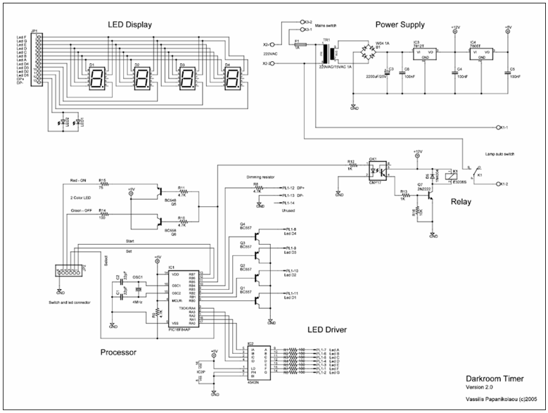
This is an enhanced version of the Darkroom Timer initially developed by Stan Ockers in 1999. Additional features have been incorporated, and the PIC code has been accordingly modified. The complete schematic, PCB layout, and silkscreen are provided in...
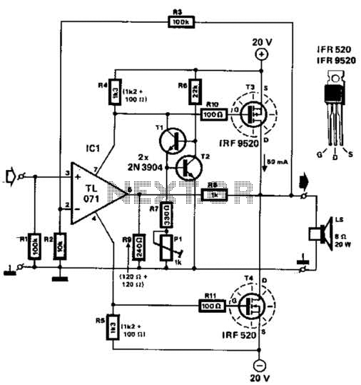
Two complementary MOSFETs are utilized to deliver 20 W into an 8-ohm load. A TL071 operational amplifier serves as the input amplifier. The MOSFETs must be equipped with a heatsink that has a thermal resistance of better than 5...
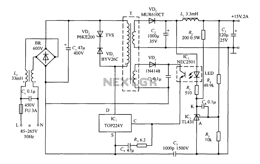
This circuit comprises a 15V TOP224Y, 2A output DC switching power supply. It utilizes three integrated circuits: IC1 is a monolithic regulator (TOP224Y), IC2 is an optocoupler (NEC2501), and IC3 is a precision voltage reference (TL431). The TL431 (IC3)...
A circuit for a bicycle horn utilizing a low-cost telecom ringer chip is presented. This design can be powered by a bicycle dynamo, eliminating the need for frequently replaced batteries. The circuit includes a half-wave voltage-doubler section formed by...
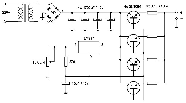
The wiring diagram illustrates that the source delivers a comparable amount of current through the parallel operation of four power transistors, which must be mounted on an effective heatsink. Voltage adjustment is achieved using an integrated LM317, which also...