
High Power Bicycle Horn

The circuit design for the bicycle horn is a practical application of a telecom ringer chip, effectively leveraging the energy produced by a bicycle dynamo. The half-wave voltage doubler circuit, consisting of diodes D1 and D2 along with capacitors C1 and C2, serves to increase the voltage supplied to the system, ensuring adequate power for the operation of IC1. The choice of a zener diode (ZD1) enhances the reliability of the circuit by providing over-voltage protection and stabilizing the voltage supplied to the integrated circuit.
The KA2411 chip operates as a tone generator, producing a dual-tone output that is essential for the horn's audible signal. The integration of transformer X1 allows for the amplification of the audio signal, facilitating a louder output through the loudspeaker. The design also accommodates alternative sound-producing elements such as a piezoceramic disk, which can be directly interfaced with the IC for a different sound profile.
For users opting for the COB version of the KA2411, specific component values have been tailored to optimize performance, ensuring that the circuit operates efficiently under various conditions. This adaptability extends the utility of the circuit beyond just a bicycle horn; it can be modified for use as a telephone ringer, demonstrating the versatility of the design. The circuit's simplicity and reliance on readily available components make it an attractive option for hobbyists and engineers alike.An interesting circuit of a bicycle horn based on a popular, low cost telecom ringer chip is described here. This circuit can be powered using the bicycle dynamo supply and does not require batteries, which need to be replaced frequently.
The section comprising diodes (D1 and D2) and capacitors (C1 and C2) forms a half-wave voltage-doubler circuit . The output of the voltage doubler is fed to capacitor C3 via resistor R1. The maximum DC supply that can be applied to the input terminals of IC1 is 28V. Therefore zener diode ZD1 is added to the circuit for protection and voltage regulation. The remainder of the circuit is the tone generator based on IC1 (KA2411). The dual-tone output signal from pin 8 of IC1 is fed to the primary of transformer X1 (same as used in transistor radios) via capacitor C6. The secondary of X1 is connected to a loudspeaker directly. In case you are interested in connecting a piezoceramic element in place of the loudspeaker, remove capacitor C6, transformer X1, and the loudspeaker.
Connect one end of the piezoceramic disk to pin 5 of IC1 and the other end to pin 8 of IC1 through a 1/4W, 1-kiloohm resistor. IC1 KA2411 is also available in COB style, with the same pin configuration. Both packages work equally well. However, to get the best results with the COB package, change values of resistors R2 through R4 to 330-kilo-ohm, capacitor C4 to 0.
47 µF, 63V electrolytic (positive end to pin 3 of IC1), and C5 to 0. 005 µF, 63V. This bicycle horn project can also be used as a telephone extra ringer by just removing all components on the left side of capacitor C3 and connecting the circuit shown in Fig. 2 to the terminals of capacitor C3. 🔗 External reference
Related Circuits
A 567 IC tone decoder/detector can be utilized to construct a remote control or intercom system. This circuit is capable of controlling a relay or transmitting an audio signal. The 567 IC is a versatile integrated circuit designed for tone...
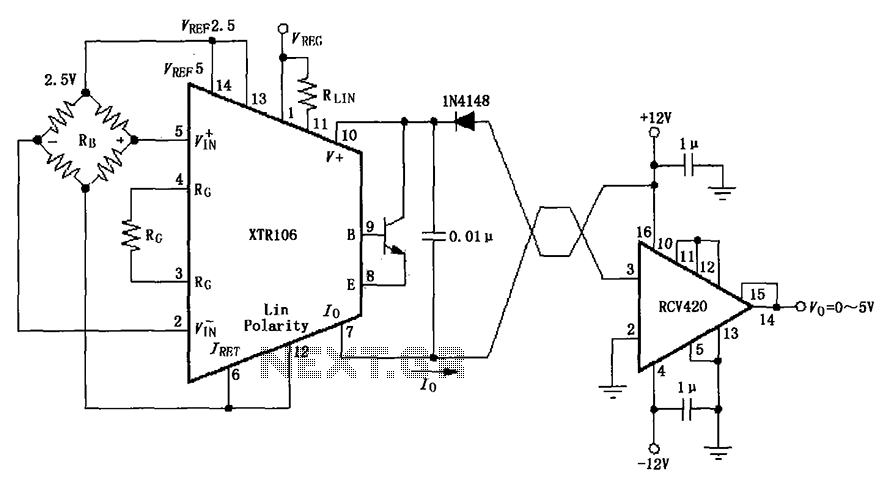
The IN4148 series diode is connected in the V+ line and configured in a loop to prevent damage from reverse voltage conditions. The diode exhibits a forward voltage drop of approximately 0.7V, which affects the supply voltage. The circuit...
The listed currents represent maximum values, and the actual current consumption will vary based on the circuit's operation. This precludes the simple use of a resistor in series to reduce voltage from 12 volts to 9 volts for powering...
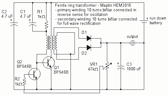
How to create a Joule Thief circuit to power a clock, including circuit details and tips for construction. The Joule Thief circuit is a simple and efficient boost converter that allows the extraction of usable voltage from low-voltage sources, such...
Control RGB LED strips via a USB or Ethernet interface. These strips consume a significant amount of power, and the mass-produced controllers are inadequate. The goal is to have independently controllable "zones," allowing this device to power one or...
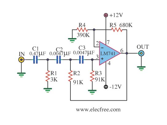
This is a simple high-pass filter that performs filtering at high frequencies. It can only change these frequencies using the IC 741, which is an integrated circuit operational amplifier used in the circuit. The high-pass filter designed with the IC...