
Mosfet Power Amplifier Circuit

The circuit employs two complementary MOSFETs configured in a push-pull arrangement to efficiently drive an 8-ohm load, delivering a total output power of 20 W. This configuration allows for improved linearity and reduced distortion, making it suitable for audio amplification applications. The choice of MOSFETs ensures high efficiency and thermal performance, which is critical in maintaining the integrity of the audio signal.
The TL071 operational amplifier is chosen for its low noise and high gain characteristics, making it an ideal candidate for the input stage of the amplifier circuit. The op-amp is configured in a non-inverting configuration to amplify the input audio signal before it is fed into the MOSFETs. Proper biasing of the op-amp is essential to ensure optimal performance and minimize distortion.
Thermal management is a crucial aspect of this design. The selected MOSFETs must be mounted on a heatsink with a thermal resistance of less than 5 °C/W to dissipate heat effectively. This ensures that the MOSFETs operate within their safe temperature limits, preventing thermal runaway and ensuring reliable operation over extended periods.
The circuit is designed to maintain a total harmonic distortion (THD) of less than 0.15% across a frequency range of 100 Hz to 10 kHz. This specification indicates that the amplifier will produce high-fidelity audio, making it suitable for high-quality audio applications. The careful selection of components and design parameters contributes to the overall performance and reliability of the amplifier circuit. Two complementary MOSFETs are used to deliver 20 W into 8 . A TL071 op amp is used as an input amplifier. The MOSFETs should be heatsinked with a heatsink of better than 5C/W capability. THD is less than 0.15% from 100 Hz to 10 kHz.
Related Circuits
Modify a zapper circuit (similar to the Hulda Clark Zapper) to produce two different frequencies. One switch should be used to set the pulse to 15Hz, and another switch to set it to 30Hz. The nominal frequency for this...
This regulated power supply can be adjusted from 3 to 25 volts and is current limited to 2 amps as shown, but may be increased to 3 amps or more by selecting a smaller current sense resistor (0.3 ohm)....
This diagram originates from the Progressive Communications Receiver featured in most recent ARRL Handbooks. The amplifier is utilized wherever an intermediate frequency (IF) amplifier is necessary. W6BKY has published an article on Hamradio-online that details the construction of this...
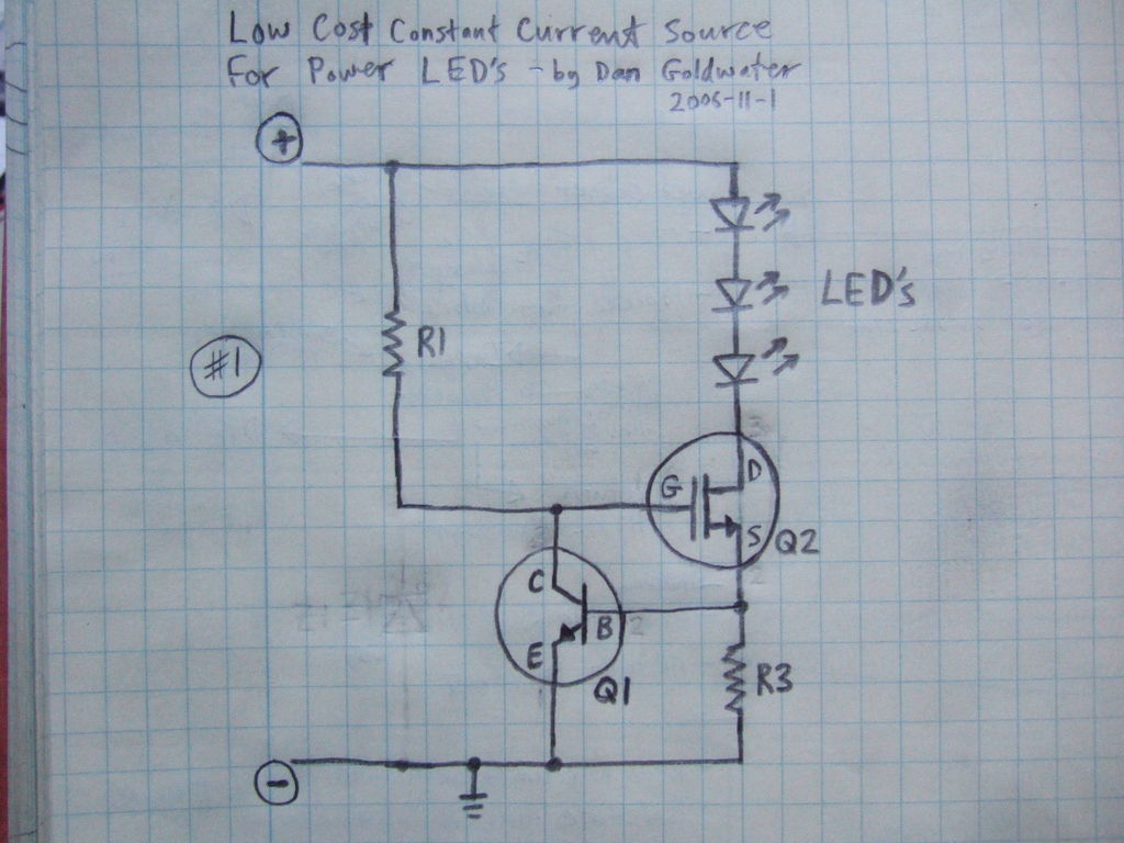
Here is a simple and inexpensive ($1) LED driver circuit. The circuit functions as a constant current source, ensuring that the LED maintains consistent brightness. The LED driver circuit is designed to provide a stable current to the LED, which...
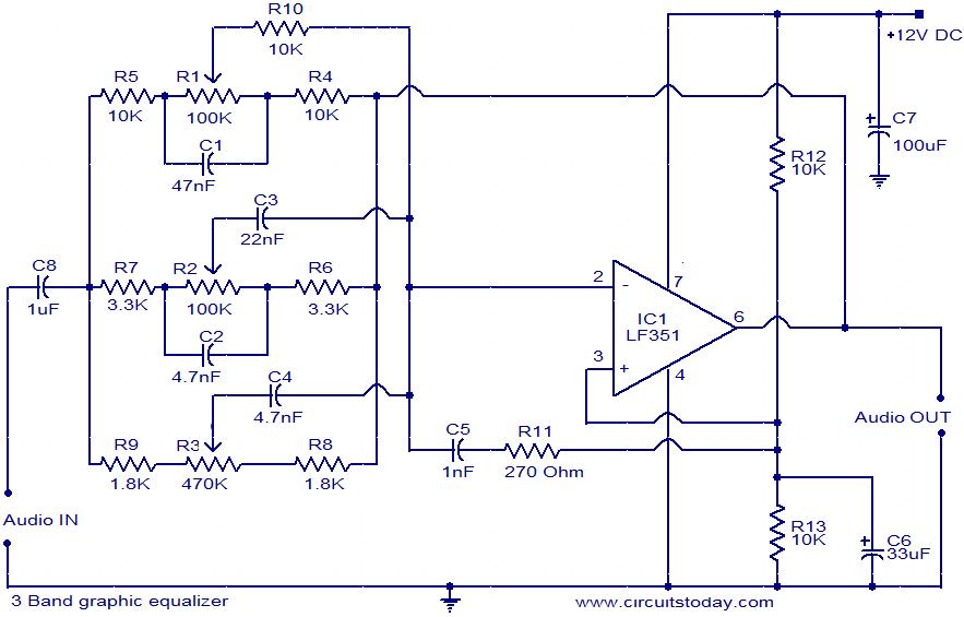
This document presents the circuit diagram of a simple three-band graphic equalizer that utilizes a single integrated circuit (IC) and a few additional components. The IC employed in this design is the LF351, which is a wide bandwidth single...
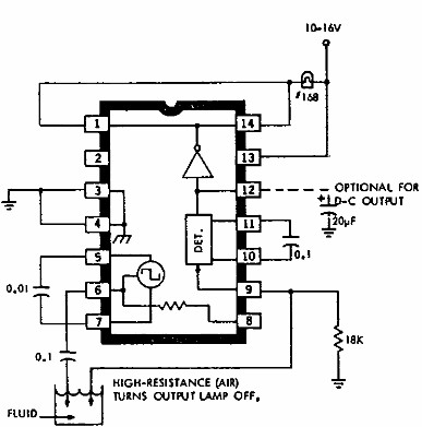
This electronic liquid detector circuit diagram utilizes the ULN2429A monolithic bipolar integrated circuit, which is designed to detect the presence or absence of various types of liquids. The detection mechanism involves comparing the resistance of a probe immersed in...