
Sun-powered alarm
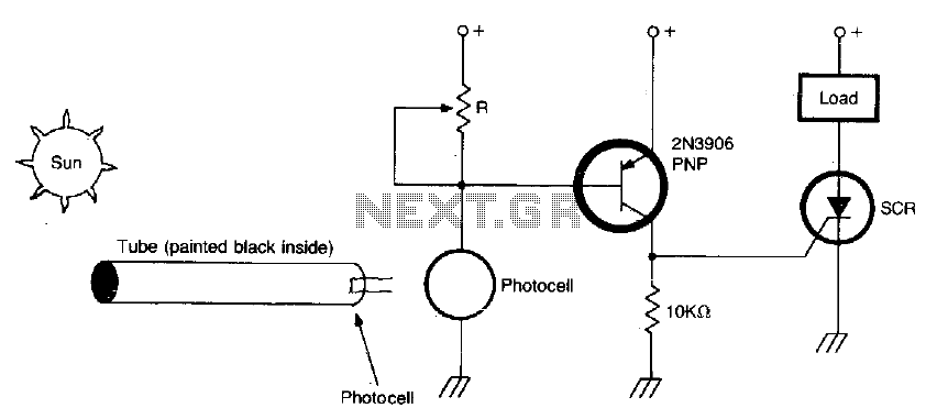
The circuit utilizes a photocell (photoresistor) as the primary sensor to detect ambient light levels. When the intensity of sunlight reaches a predetermined threshold set by the potentiometer R, the circuit initiates an alarm signal. The photocell's resistance decreases with increasing light intensity, which in turn affects the voltage across the circuit.
The potentiometer R is a variable resistor that allows for fine-tuning of the light sensitivity. By adjusting this component, the user can define the specific light level at which the alarm will activate, ensuring that the circuit is responsive to the desired ambient conditions.
The inclusion of a painted tube, specifically designed with a black interior, serves to enhance the photocell's sensitivity to sunlight. This tube can help to concentrate the light entering the photocell, effectively increasing its response to sunlight while minimizing interference from surrounding light sources. The design of the tube is critical, as it must be positioned correctly to ensure optimal exposure to sunlight.
The overall circuit design may include additional components such as a transistor or relay to amplify the alarm signal, ensuring that it is loud enough to be heard in various environments. Power supply considerations should also be taken into account, with options for battery or solar power sources to enhance portability and efficiency.
In summary, this light-activated alarm circuit is a practical application of basic electronic principles, utilizing a photocell, potentiometer, and an optional focusing tube to create a responsive and adjustable alarm system.Circuit turns on when light (sunlight) strikes photocell. Potentiometer R sets light level at which the alarm sounds Painted tube (black on inside) may be used on photocell to aim at the sun. 🔗 External reference
Related Circuits

To check the battery in a car, an easy circuit utilizing the IC CA3140 and a transistor is employed. The voltage level of an automobile battery is influenced by many factors, and if it is high... The circuit for checking...
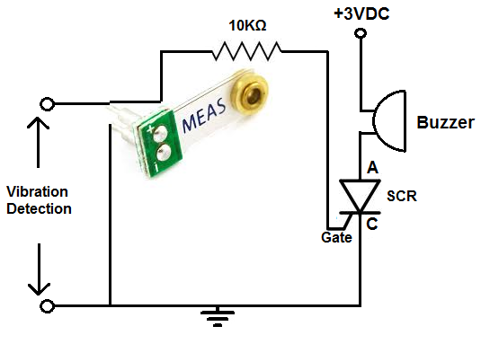
This alarm is designed for use in a room or area that should typically remain motionless. In an environment devoid of movement, no vibrations will be detected, and the alarm will remain inactive. However, once the circuit identifies a...

Have you ever observed the stairs to an upper story in your house transform into a waterfall? Or perhaps you returned home to find your aquarium fish attempting to swim across the carpet? For your sake, it is hoped...

A motion detection alarm circuit utilizing a PIR sensor for motion detection. When movement is detected by the PIR sensor, it triggers a delay circuit, Q1, and other components. The motion detection alarm circuit is designed to provide an alert...
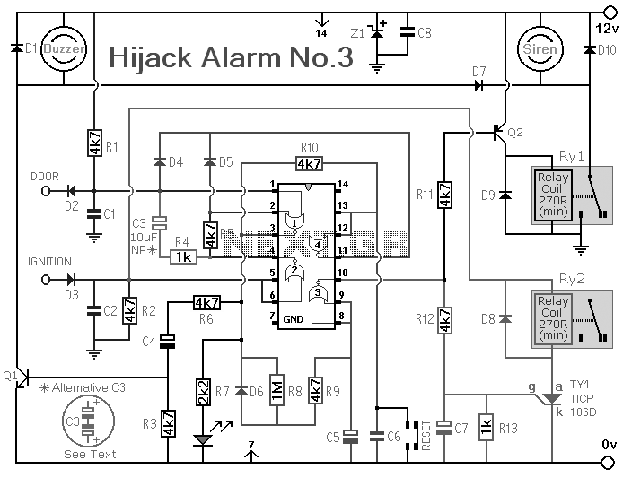
The Vehicle Anti-Hijack Alarm No3 is designed specifically for scenarios where a hijacker forcibly removes the driver from the vehicle. If any door is opened while the ignition is on, the circuit will activate. The Vehicle Anti-Hijack Alarm No3...
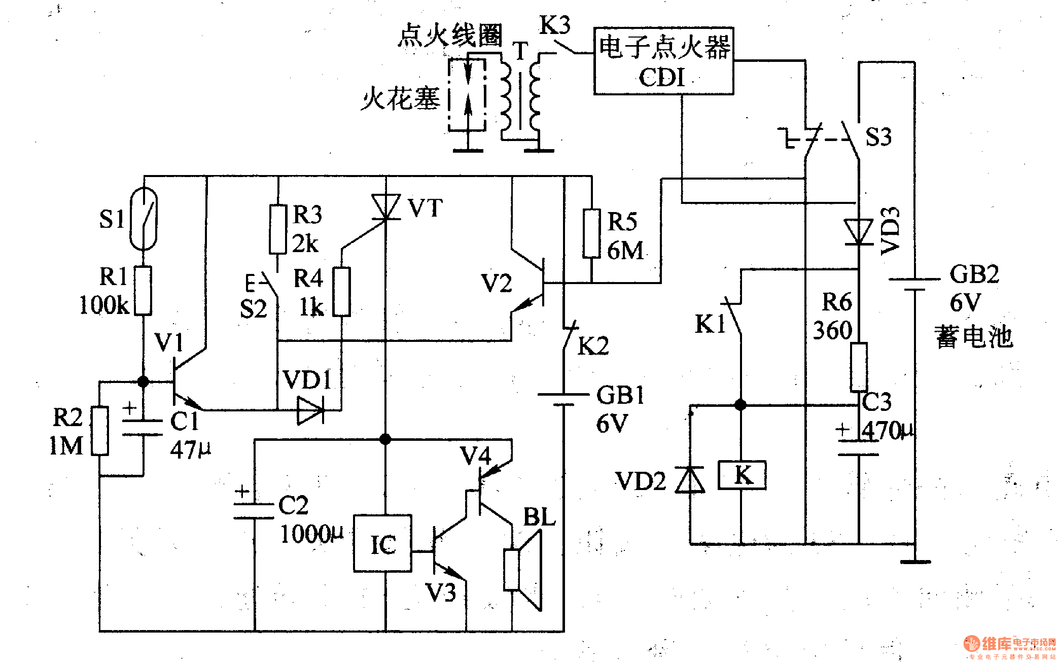
The multi-function motorcycle anti-theft alarm discussed in this article is suitable for anti-theft applications for all two-wheel motorcycles. The motorcycle anti-theft alarm circuit consists of a mobile delay alarm circuit, an ignition switch ground wire break alarm circuit, and...