
Scoring Game Circuit-DescriptionCircuit PartsDiagram
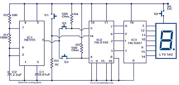
The scoring game circuit is designed to track and display scores in a gaming environment. The primary components of this circuit typically include a microcontroller, a score display (such as a seven-segment display), input buttons for score adjustments, and a power supply.
The microcontroller serves as the central processing unit, where the game logic is implemented. It receives input from the buttons, which are used to increase or decrease the score. The circuit diagram will illustrate the connections between the microcontroller, the display, and the buttons.
The score display is connected to the microcontroller through a series of output pins, which send signals to determine which segments of the display should be illuminated. Commonly, a seven-segment display is used to visually represent the score, with each segment corresponding to a specific numeral.
Power supply considerations are essential for the circuit, ensuring that all components operate within their specified voltage and current ratings. A regulated power supply may be employed to provide a stable voltage to the microcontroller and display.
Additional features may include sound effects for score adjustments, which can be achieved by integrating a small speaker or buzzer connected to the microcontroller. This adds an auditory feedback element, enhancing the user experience during gameplay.
Overall, the scoring game circuit combines various electronic components to create an interactive and engaging scoring system suitable for games of different types. The schematic representation of the circuit will detail the interconnections and functional relationships between all components, ensuring clarity in the design and implementation process.A scoring game circuit is explained with circuit diagram, and circuit parts.. 🔗 External reference
Related Circuits
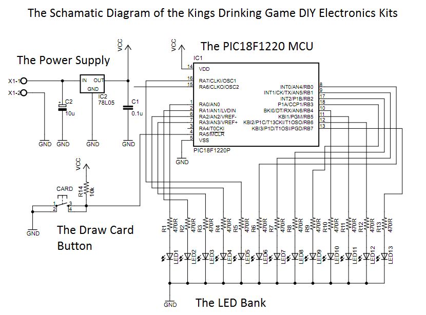
Should I cut the blue wire... or the red...? This is a very common phrase in many movies when the action hero has a bomb in front of him with little time left and he has to choose which...
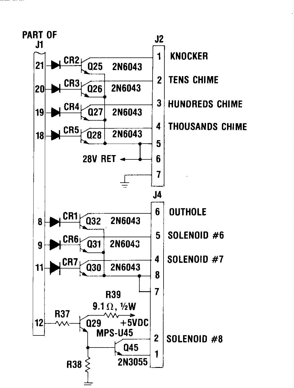
A proposed solution is being tested to prevent overvoltage from reaching the irreplaceable IC U5 - A1752CF after either the switch drives or returns experience a static electric shock or encounter the 24VDC solenoid bus. The protection mechanism is...
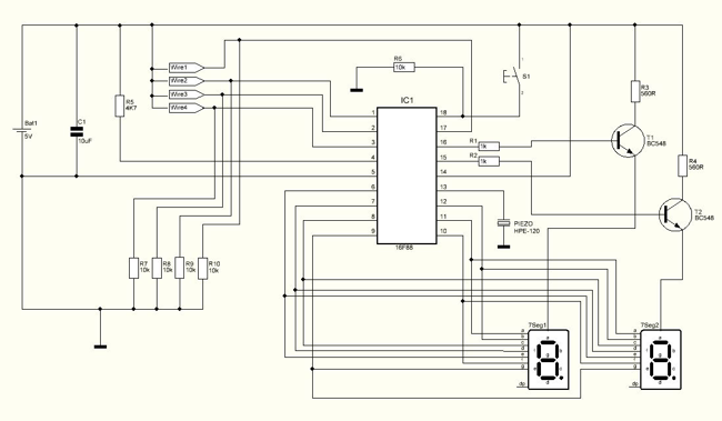
This circuit was designed approximately four months ago and has been developed into a kit for others to use. The circuit in question appears to be a well-thought-out design that has been packaged into a kit format, making it accessible...
The circuit below turns on a light corresponding to the first of several buttons pressed in a "Who's First" game. Three stages are shown but the circuit can be extended to include any number of buttons and lamps. Three...

The objective of the circuit is to create an electronic dice using the functionality of a 555 timer integrated circuit operating in astable mode. The electronic dice circuit utilizes a 555 timer configured in astable mode to generate a series...
The objective is to enhance information transmission through the distribution of articles. For any issues related to article content, copyright, or other concerns, please contact us via email at [email protected] within 15 days. Prompt action will be taken to...