
Electronically Designed Dice Game Circuit by LM555

The electronic dice circuit utilizes a 555 timer configured in astable mode to generate a series of pulses that simulate the rolling of a dice. The frequency of these pulses can be adjusted to control the speed of the dice roll. The circuit typically includes a few key components: resistors, capacitors, and possibly a display mechanism such as LEDs or a seven-segment display to represent the dice values.
In this configuration, the timing components—resistors (R1, R2) and a capacitor (C1)—determine the frequency of oscillation. The output from the 555 timer is a square wave signal that can be used to trigger the display. When the circuit is powered, the 555 timer continuously switches its output between high and low states, creating a rapid sequence of flashes on the display.
To represent the values of a dice (1 through 6), a decoding mechanism is often employed. This can be achieved using a binary decoder or a simple microcontroller that interprets the output from the 555 timer. The output can be mapped to the corresponding numbers displayed, ensuring that only one value is shown at a time.
The circuit may also include a reset button to stop the rolling effect and latch the current value displayed. This feature allows users to "roll" the dice by pressing a button, which starts the oscillation, and then pressing the reset button to freeze the display at a random value.
Power supply considerations are important; the circuit can typically operate on a standard voltage, such as 5V or 9V, depending on the specifications of the 555 timer and the display components used. Proper decoupling capacitors should be included to filter noise and ensure stable operation.
Overall, this electronic dice circuit is a practical application of the 555 timer in astable mode, demonstrating its versatility in generating random outputs suitable for gaming applications.The objective of the circuit is to build an electronic dice based on the functions of a 555 timer integrated circuit that operates in the astable mode. LM.. 🔗 External reference
Related Circuits
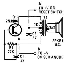
This is a simple low-level noise maker that is ideally suited for certain alarm applications. When the sounder is located in another part of the building, the sound level is loud enough to be heard but is not loud...
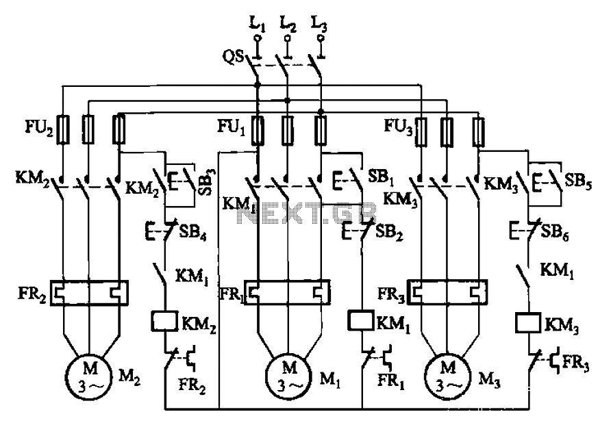
The circuit shown in Figure 3-89 illustrates a system where starting motor M1 allows motors M2 and M3 to initiate operation. Upon shutdown, motor Mz can be stopped first; however, once motor M1 is stopped (by pressing switch SB2),...
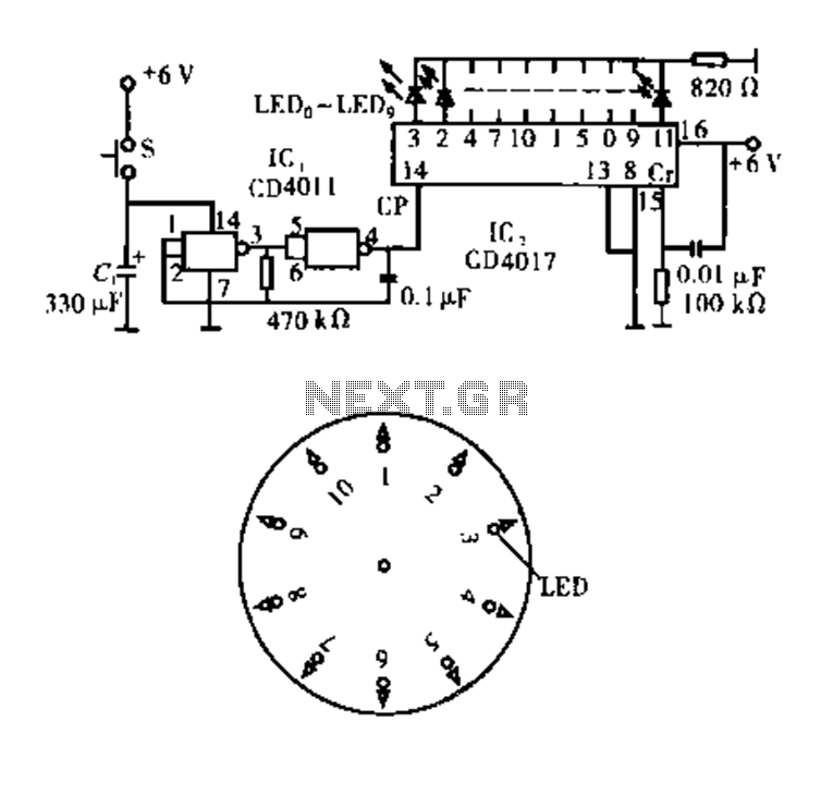
Dot Award. This circuit is tested and functional. The circuit consists of two integrated circuits (ICs). IC1 serves as a pulse source, activated by a momentary button switch (S). When the button is pressed, it charges capacitor C1, which...
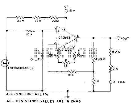
The circuit requires a 15-volt power supply and employs a precision operational amplifier, CA3193 BiMOS, to amplify the generated signal by more than 500 times. Three 22-megohm resistors are utilized to ensure a large-scale output in the event of...
A Super GameBoy was acquired, but it has been observed that the sound pitch is significantly higher than that of an original GameBoy. This discrepancy arises due to a mismatch in CPU clock frequencies: 4.194304 MHz for the original...
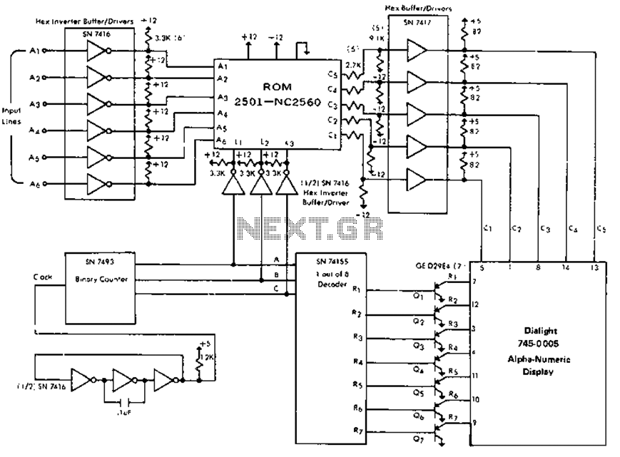
The circuit is capable of driving the company's Dialight 745-0005 monitor, which features a 64-character alphanumeric display. It generates 0-second and 1-second input signals on lines A1 through A6 based on the phase response of the desired characters, utilizing...
Warning: include(partials/cookie-banner.php): Failed to open stream: Permission denied in /var/www/html/nextgr/view-circuit.php on line 713
Warning: include(): Failed opening 'partials/cookie-banner.php' for inclusion (include_path='.:/usr/share/php') in /var/www/html/nextgr/view-circuit.php on line 713