
SCR Applications

SCRs, or Silicon Controlled Rectifiers, are critical components in modern electronic circuits, particularly in power control applications. Their ability to manage large currents with minimal gate current input makes them ideal for various industrial uses. The SCR's operation is based on its bistable nature, allowing it to switch between conducting and non-conducting states efficiently. This property is leveraged in both AC and DC applications, providing flexibility in power management.
In AC applications, SCRs can be triggered at specific angles relative to the voltage waveform, allowing for precise control over power delivery to inductive loads. The firing angle adjustment is a key aspect of phase control, where the load voltage and current can be manipulated to optimize performance. The incorporation of a free-wheeling diode enhances the load current waveform, ensuring smoother operation and reducing stress on the SCR.
In DC applications, SCRs function through on-off control, where the duration of conduction is varied to regulate power output. This technique is particularly useful in applications requiring precise power management, such as battery chargers and motor controllers. The ability of SCRs to handle high power levels has led to their widespread adoption in inverter circuits, which convert DC to AC power. This conversion is essential for numerous applications, including variable frequency drives for motors, heating systems, and lighting controls.
Overall, the versatility and efficiency of SCRs make them indispensable in modern electronic designs, where reliable power control is paramount. Their applications span various industries, from consumer electronics to industrial automation, highlighting their critical role in contemporary power electronics.The ability of an SCR to control large currents to a load by means of small gate current makes the device very useful in switching and control applications. A few of the possible applications for the SCR are listed in the introduction to SCR blog post. Here we will consider six applications of SCR like power control, switching, zero-voltage switch ing, over-voltage protection, pulse circuits and battery charging regulator. Because of the bistable characteristics of semiconductor devices, whereby they can be switched on and off, and the efficiency of gate control to trigger such devices, the SCRs are ideally suited for many industrial applications. SCRs have got specific advantages over saturable core reactors and gas tubes owing to their compactness, reliability, low losses, and speedy turn-on and turn-off.
The bistable states (conducting and non-conducting) of the SCR and the property that enables fast transition from one state to the other are made use of in the control of power in both ac and dc circuits. In ac circuits the SCR can be turned-on by the gate at any angle ± with respect to applied voltage. This angle ± is called the firing angle and power control is obtained by varying the firing angle. This is known as phase control. A simple half-wave circuit is shown in figure a. for illustrating the principle of phase control for an inductive load. The load current, load voltage and supply voltage waveforms are shown in figure b. The SCR will turn-off by natural commutation when the current becomes zero. Angle ² is known as the conduction angle. By varying the firing angle a, the rms value of the loadvoltage can be varied. The power consumed by the load decreases with the increase in firing angle a. The reactive power input from the supply increases with the increase in firing angle. The load current wave-form can be improved by connecting a free-wheeling diode D1, as shown by the dotted line in fig-a.
With this diode, SCR will be turned-off as soon as the input voltage polarity reverses. After that, the load current will free wheel through the diode and a reverse voltage will appear across the SCR. The main advantage of phase control is that the load current passes through a natural zero point during every half cycle.
So, the device turns-off by itself at the end of every conducting period and no other commutating circuit is required. Power control in dc circuits is obtained by varying the duration of on-time and off-time of thedevice and such a mode of operation is called on-off control or chopper control.
Another important application of SCRs is in inverters, used for converting dc into ac. The input frequency is related to the triggering frequency of SCRs in the inverters. Thus, variable frequency supply can be easily obtained and used for speed control of ac motors, induction heating, electrolytic cleaning, fluorescent lighting and several other applications. Because of the large power-handling capacity of the SCRs, the SCR controlled inverter has more or less replaced motor-generator sets and magnetic frequency multipliers for gener ating high frequency at large power ratings.
A commonly used circuit for controlling power in load RL using two SCRs is shown in figure. Potentiometer R controls the angle of conduction of the two SCRs. The greater the resistance of the pot, lesser will be the voltage across capacitors C1 and C2 and hence smaller will be the time duration of conduction of SCR1 and SCR2 during a cycle. During positive half cycle capacitor C2 gets charged throughdiode D1, pot R, and diode D4. When the capacitor gets fully charged, (charge on the capacitor depending upon the value of R) it discharges through Zener diode Z.
This gives a pulse to the primary and thereby secondary of the transformer T2. Thus SCR2, which is forward biased, is turned on and conducts through load RL. During negative half cycle similar action takes place due to chargin 🔗 External reference
Related Circuits
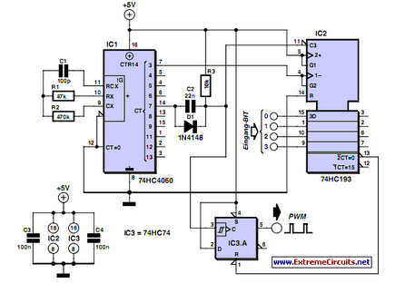
PWM waveforms are frequently utilized to regulate the speed of DC motors. The duty cycle of the digital waveform can be defined using an adjustable parameter. PWM (Pulse Width Modulation) is a technique employed to control the power delivered to...
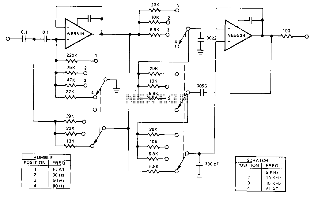
This is a variable bandpass amplifier with adjustable low and high-frequency cutoffs. A variable bandpass amplifier is designed to allow a specific range of frequencies to pass through while attenuating frequencies outside this range. The adjustable low and high-frequency cutoffs...
PWM waveforms are widely utilized to regulate the speed of DC motors. The duty cycle of the digital waveform can be established either through an adjustable analog voltage level (as seen in a NE555-based PWM generator) or through digital...
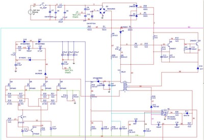
A Power Factor Correction (PFC) board has been obtained from an old Sun Microsystems Spark450 power supply (part number 300-1359-xx). This board contains all necessary components for a 650-watt inverter. However, the complete PFC circuit is not fully detailed...
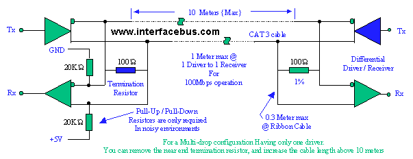
The circuit is designed to provide an output voltage swing of 350 mV at speeds exceeding 400 Mbps into a 100-ohm load over a distance of approximately 10 meters. Low-Voltage Differential Signaling (LVDS) is an electrical specification that serves...
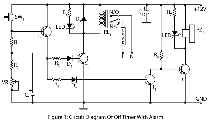
An off timer with an alarm is a straightforward project designed to indicate the end of a specified time period. The circuit utilizes four transistors. It includes a circuit diagram along with a parts list and a description of...