
Discrete PWM Generator Circuit
PWM (Pulse Width Modulation) is an effective technique for controlling the speed of DC motors by varying the average power delivered to the motor. The fundamental concept involves switching the power to the motor on and off at a high frequency, with the ratio of the "on" time to the "off" time (known as the duty cycle) determining the effective voltage and current supplied to the motor.
In a NE555-based PWM generator, the duty cycle can be adjusted by varying the resistance and capacitance in the timing circuit. The NE555 timer operates in astable mode to generate a continuous square wave output. By changing the resistor values or the capacitor, the mark-to-space ratio can be modified, thus controlling the motor speed effectively.
For applications requiring digital control, microcontrollers are commonly employed to generate PWM signals. The timer/counter modules within these microcontrollers can be configured to produce PWM outputs with precise duty cycles, allowing for fine control over motor speed. The programming of the microcontroller can be tailored to adjust the PWM frequency and duty cycle in response to user inputs or feedback from sensors.
In scenarios where a microcontroller is not used, discrete logic components such as flip-flops, resistors, and capacitors can be assembled to create a simple PWM generator. For instance, a 555 timer can be used in conjunction with a few discrete components to achieve similar functionality. Additionally, digital counters can be employed to create a PWM signal by toggling the output based on a defined count.
Overall, PWM is a versatile method for controlling DC motors, providing both analog and digital options for signal generation, and can be implemented in various ways depending on the specific requirements of the application.PWM waveforms are commonly used to control the speed of DC motors. The mark/space ratio of the digital wave-form can be defined either by using an adjustable analogue voltage level (in the case of a NE555 based PWM generator) or digitally using binary values. Digitally derived PWM waveforms are most often produced by the timer/counter modules in microcontrollers but if you do not want to include a microcontroller in your circuit it s also quite simple to generate the signals using discrete logic components..
🔗 External reference
Related Circuits
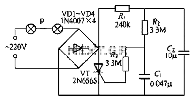
A simple and easy-to-implement one-way flashing lights string controller is designed for small shop or home decoration. This device utilizes a thyristor-based dimmer circuit, which operates effectively by managing large capacitance. The circuit includes a ten-microfarad capacitor connected to...
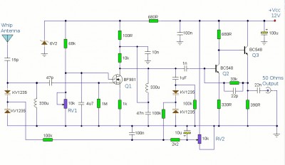
This is a booster antenna circuit designed for frequencies ranging from 550 kHz to 1650 kHz, aimed at amplifying signals received from a telescopic antenna. It covers the medium waveband within this frequency range. To drive low impedance (50...
This flip-flop circuit is a free-running astable multivibrator, with the bases and collectors of both emitter-biased transistors directly coupled to each other. The switching action is facilitated by a capacitor in each emitter circuit. This configuration produces triangular waves...
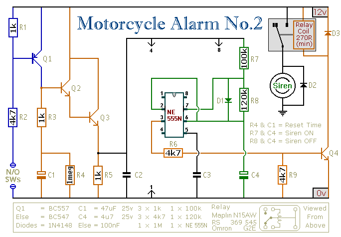
This circuit provides an intermittent siren output with an automatic reset function. It can be manually activated using a key switch or a concealed switch, and it can also be configured to engage automatically when the ignition is turned...
The tuner is programmable via I²C-Bus and provides a FBAS signal at its output. There is also the homepage of Georg Acher containing information about this tuner. A control circuit has been developed for this tuner using the AT89C2051...
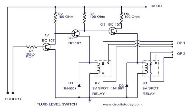
A simple liquid level switch circuit with diagram and schematic. This can also be used as a water level switch, fluid level switch, float level switch, and tank level switch. The liquid level switch circuit is designed to detect the...
Warning: include(partials/cookie-banner.php): Failed to open stream: Permission denied in /var/www/html/nextgr/view-circuit.php on line 713
Warning: include(): Failed opening 'partials/cookie-banner.php' for inclusion (include_path='.:/usr/share/php') in /var/www/html/nextgr/view-circuit.php on line 713