
Scr Capacitor Turn-Off Circuit
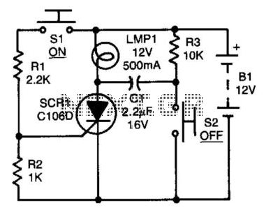
In this circuit, the silicon-controlled rectifier (SCR) plays a crucial role in controlling the flow of current. Initially, when the SCR is turned on, it allows current to flow through the circuit. The capacitor CI, connected through resistor R3, charges up to the supply voltage, enabling the SCR to remain in its conductive state.
When switch S2 is closed, it creates a path to ground for the positive terminal of CI. This action causes the voltage at the anode of the SCR to drop momentarily below zero, effectively reverse-biasing the SCR. This condition is essential for turning off the SCR, as it disrupts the current flow through the device. The rapid discharge of CI ensures that the SCR remains off for a sufficient duration, preventing any unintended re-triggering.
The choice of a non-polarized capacitor CI is critical in this design, as it allows for bidirectional current flow without the risk of damage due to incorrect polarity. This feature enhances the circuit's reliability and performance, particularly in applications where the voltage polarity may change.
Overall, this configuration demonstrates a practical method for controlling an SCR using a capacitor discharge, providing a reliable means to manage the switching characteristics of the SCR in various electronic applications. After the SCR turns on, CI charges up to almost the full supply voltage via R3 and the anode of the SCR. Whe n S2 is subsequently closed, it clamps the positive end of CI to ground, and the charge on CI forces the anode of the SCR to swing negative momentarily, thereby reverse-biasing the SCR and causing it to turn off. The capacitor"s charge bleeds away rapidly, but it has to hold the SCR"s anode negative for only a few /is to ensure turn-off.
CI must be a nonpolarized type. 🔗 External reference
Related Circuits
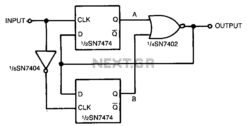
An input signal drives both SN74 D-type flip-flops, which are positive edge-triggered devices. A low-to-high input signal transition triggers the A flip-flop, while a high-to-low input signal transition triggers the B flip-flop via the SN7404 inverter. Either flip-flop in...
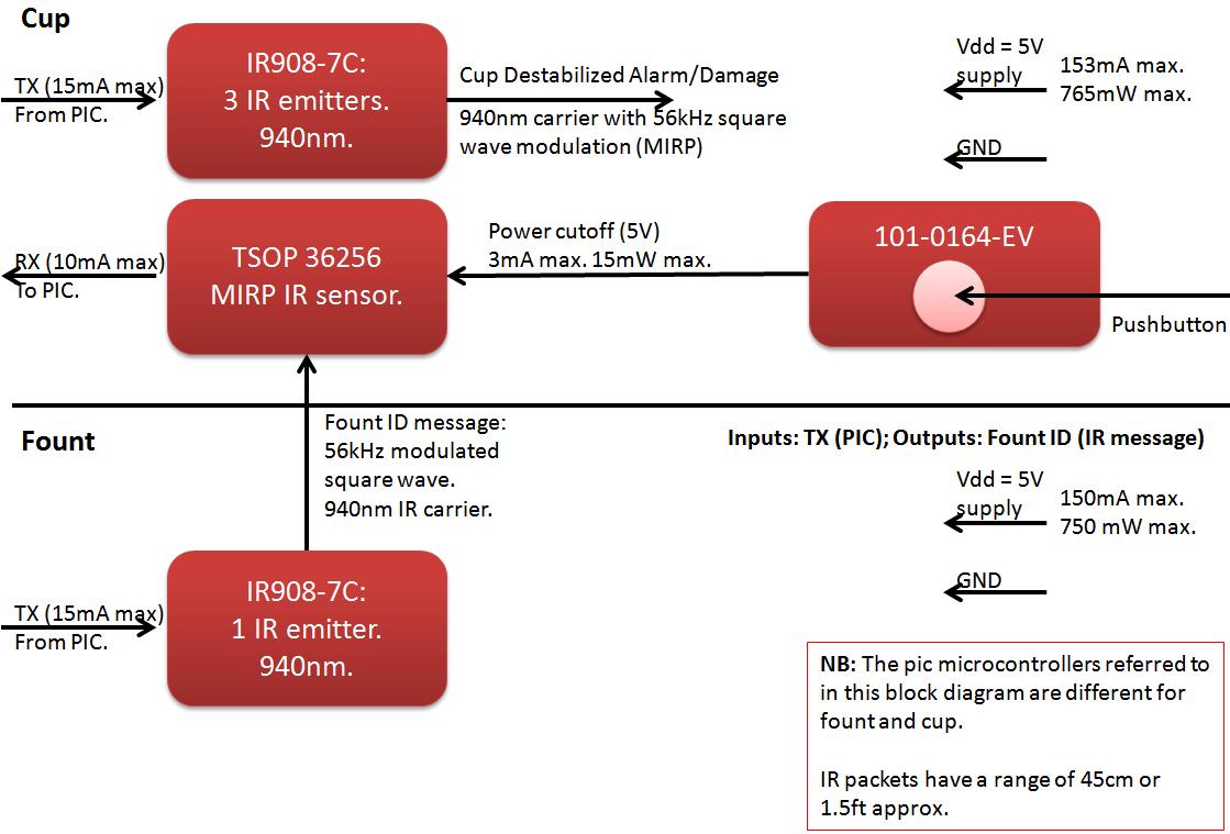
The founts must notify the server when the cup is taken from the fount or when the opponent's cup is poured into the team's cup. The implementation of the actual pouring action is at the discretion of the team....
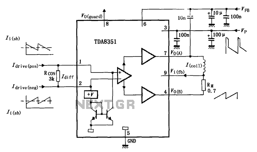
The figure illustrates the actual application circuit for the TDA8351/8356. In this circuit, a 50V voltage feedback (VFB) is connected in series with a 33-ohm resistor. Signals are input at pins 1 and 2, where pin 1 receives a...
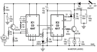
The following circuit illustrates an Infrared Toy Car Motor Controller Circuit Diagram. This circuit is based on the 4017 IC. Features: operating at .. The Infrared Toy Car Motor Controller Circuit utilizes a 4017 Decade Counter IC, which is integral...

The remote control circuit consists of two main components: the transmitter and the receiver. A simple schematic diagram illustrates the remote control setup. The transmitter circuit utilizes a NE555 timer IC to generate a specific frequency. The receiver circuit...

Automatic electronic refrigerator deodorant sterilization circuit The automatic electronic refrigerator deodorant sterilization circuit is designed to eliminate odors and sterilize the interior of a refrigerator. This circuit typically employs a combination of sensors, microcontrollers, and sterilization techniques to achieve effective...