
TDA8351 8356 application circuit
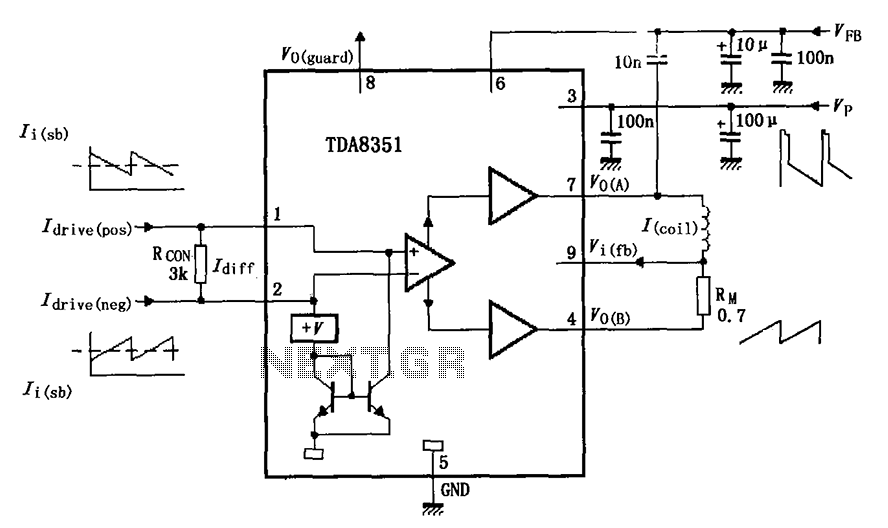
The TDA8351/8356 application circuit is designed for use in television and display systems, where precise control of deflection currents is essential for image stability and quality. The circuit operates by generating opposing sawtooth voltage signals at pins 1 and 2, which are crucial for controlling the deflection coils in cathode-ray tubes (CRTs) or similar display technologies. The resistor Rcon, situated between the input pins, plays a vital role in regulating the current through the deflection coils, ensuring accurate deflection of the electron beam.
The internal differential amplifier processes the input signals, amplifying the difference between them, which is then fed into a push-pull output stage. This configuration allows for efficient driving of the deflection coils, providing a strong and responsive control signal. The output at pin 7 produces a positive sawtooth waveform, while pin 4 delivers the corresponding negative sawtooth waveform, creating the necessary alternating current for deflection.
The inclusion of the feedback resistor RM is critical for improving the linearity of the output waveforms. By connecting RM in series with the deflection coil, the circuit can adjust the feedback voltage at pin 9, enhancing the performance of the sawtooth generator. This feedback loop not only stabilizes the output but also broadens the dynamic range, allowing for more precise control over the deflection process.
Overall, the TDA8351/8356 application circuit exemplifies a sophisticated approach to managing voltage signals for display applications, ensuring that the generated waveforms are both linear and dynamic, which is essential for high-quality image rendering. As shown in the figure shows the actual application circuit TDA8351/8356, when the 50V VFB 60V, VFB in series with the input of a 33 resistor. Signals are input 1,2 feet, these are two sawtooth voltage signal opposite in phase, positive sawtooth voltage input pin 1, pin 2 negative sawtooth voltage input. 1,2 feet between a resistor in parallel Rcon to determine the deflection current through the coil. After an internal signal of the differential amplifier and push-pull power amplifier output to the deflection by a 7,4 feet across the coil.
7 feet sawtooth voltage waveform pulse, 4 feet sawtooth voltage waveform is negative. RM resistor in series with the deflection coil, provided by the feedback voltage input pin 9, the linear sawtooth output is improved, and expand the dynamic range of the sawtooth wave.
Related Circuits
Prior to the test point, there is an AD744 operational amplifier with its output connected to a 10nF capacitor. Following this, a 1kΩ resistor connects to ground. From the junction where the capacitor and resistor meet, a 4.7kΩ resistor...
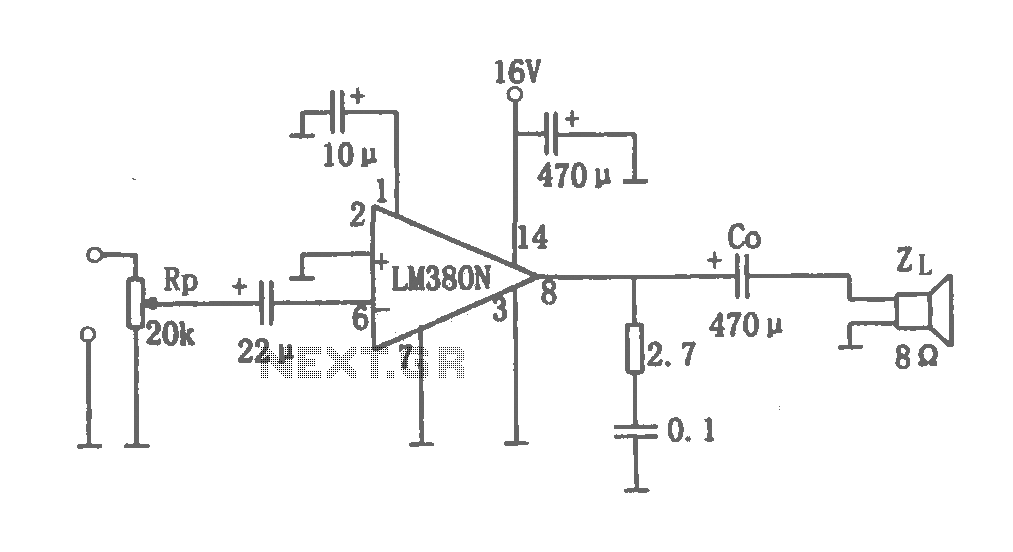
This document details a 2W audio power amplifier circuit that utilizes a 14-pin LM380 package as the amplification element. The input signal is managed by a volume control potentiometer (Rp) rated at 20k ohms, with a coupling capacitance of...
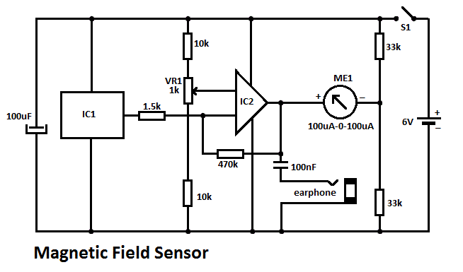
This DIY magnetic field sensor circuit is straightforward and capable of detecting both static magnetic fields and those that vary at audio frequencies. The unit is designed to be user-friendly and efficient. The magnetic field sensor circuit typically employs a...

This game can be played individually or with friends. The circuit consists of a timer IC, two decade counters, and a display driver paired with a 7-segment display. The objective of the game is straightforward: the player who reaches...
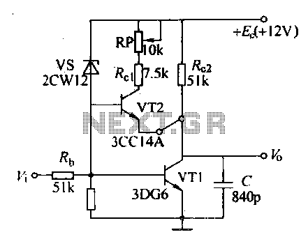
Various sawtooth voltage generators utilize the principle of capacitor charging and discharging to produce sawtooth waveforms in both forward and reverse directions. A simple sawtooth voltage generator circuit is straightforward in design; however, it suffers from poor linearity in...
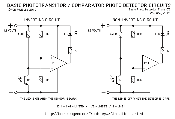
This page features basic, visible light photo-detector circuits that can be used to detect trains. These methods would normally be used with the photo sensor mounted between the rails. The described photo-detector circuits are designed to detect the presence of...