
SCR relaxation flasher

The described circuit utilizes a Silicon Controlled Rectifier (SCR) to control the discharge of a capacitor, creating a flashing effect. The operation begins when the capacitor is charged to a certain voltage level. When the SCR is triggered into the 'on' state, the capacitor discharges through the SCR, producing a flash of light or signal as desired.
The critical aspect of this circuit is the holding current of the SCR. This is the minimum current required to keep the SCR in the conducting state. Once the discharge current from the capacitor drops below this threshold, the SCR will turn off, interrupting the flow of current. At this point, the capacitor begins to recharge, preparing for the next discharge cycle. The timing of this cycle can be adjusted by varying the capacitor value or the resistance in the charging path.
An essential feature of this circuit is its ability to maintain functionality even with a degraded battery. As batteries age, their voltage and capacity may diminish, but the circuit is designed to provide a slower flashing capability, ensuring that it can still operate effectively under lower voltage conditions. This resilience makes the circuit suitable for applications where battery life is a concern, such as in portable devices or emergency lighting systems.
In summary, this SCR-based flashing circuit effectively manages the discharge and recharge cycles of a capacitor, ensuring reliable operation even as the power source degrades. Adjustments to component values can fine-tune the flashing rate and intensity, making it versatile for various applications.Flashing occurs each time the capacitor discharges through the tumed-on SCR. When the discharge current falls below the SCR holding current, the SCR turns off, and the capacitor begins charging for another cycle. The circuit will maintain a slower but good flashing capability even after considerable battery degradation. 🔗 External reference
Related Circuits
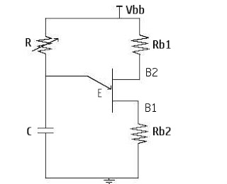
At the point Vp, the emitter triggers and turns the UJT (Uni-Junction Transistor) ON. Up to this point, the emitter is isolated and does not conduct, resulting in no current conduction between Base1 and Base2. The operation of the Uni-Junction...
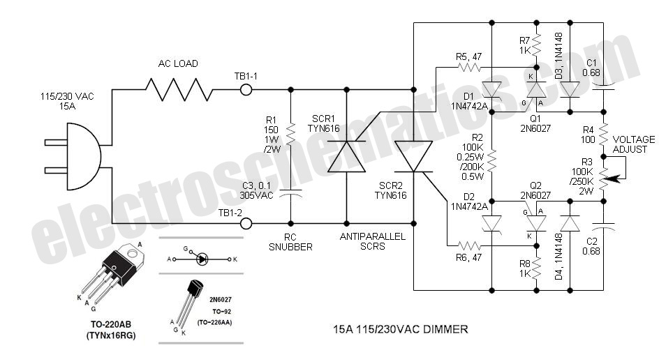
The DIAC is a 28V bidirectional trigger device commonly used in inexpensive phase control applications. Its trigger voltage is relatively high for 115VAC phase control. In the past, a similar low voltage trigger device known as a Shockley diode...
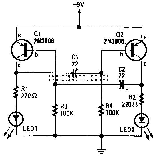
The alternating LED flasher is a two-transistor oscillator with LEDs connected to the collector of each transistor, allowing them to light in sync with the circuit's oscillations. The alternating LED flasher circuit utilizes a two-transistor oscillator configuration, which is a...
This is a simple two-transistor lamp flasher circuit that can be used to flash a 6-volt lamp. The circuit is compact and can be easily fitted into a small enclosure. It utilizes two transistors: one is an NPN BC549,...
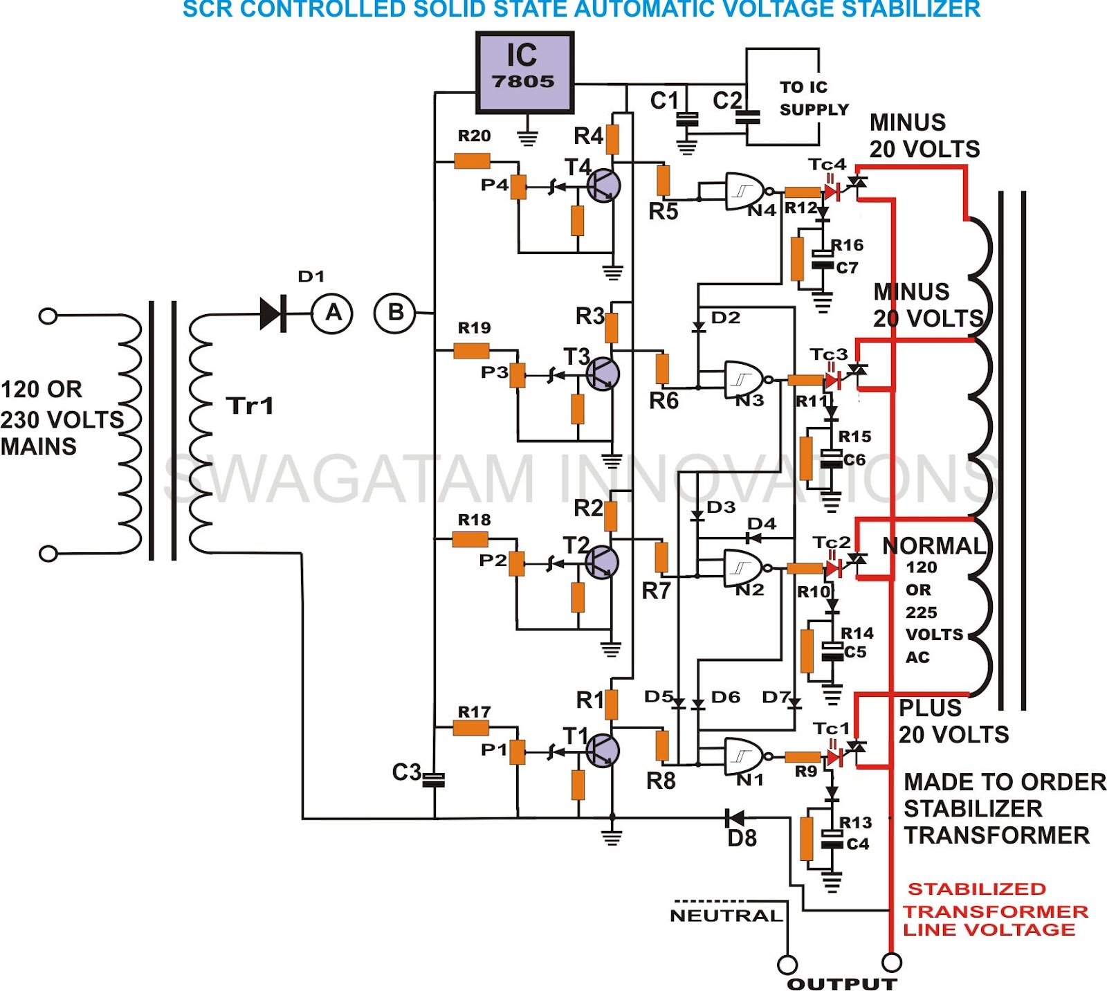
This unique and hard-to-find triac-controlled AC voltage stabilizer circuit has been specifically designed for efficient voltage stabilization. With a solid-state design, the voltage switching transitions are smooth, resulting in minimal wear and tear. The proposed circuit provides four-step voltage...
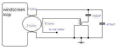
If you do not like the whip antenna on your car, you may try this alternative circuit. A one-turn loop is installed in the windscreen of the car, keeping possibly away from the metal structure of the car. This...