
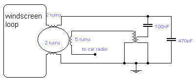
Car Windscreen Loop Antenna
The described circuit presents a novel approach to car antenna design, utilizing a one-turn loop antenna installed within the vehicle's windscreen. This design is particularly advantageous for individuals seeking to replace traditional whip antennas, which can be aesthetically unpleasing or prone to damage.
The one-turn loop antenna functions by creating a magnetic field that captures radio frequency signals, particularly in the VHF range. The loop is strategically positioned away from the vehicle's metal structure to minimize interference and maximize signal reception. The termination of the loop with a 6.5mm ring core enhances its performance in the VHF band, ensuring optimal impedance matching and signal strength.
Additionally, the circuit incorporates a secondary coil sourced from an old medium wave (MW) radio, which serves to capture both medium wave and long wave (LW) signals. This coil, originally an oscillator coil, is modified by removing all capacitors and adjusting the slug to its fully-in position. This alteration is crucial as it allows for fine-tuning of the coil's inductance, thereby improving signal reception across the desired frequency bands.
The performance of this alternative antenna system is highly dependent on the quality and characteristics of the components utilized. While many users report performance comparable to that of traditional whip antennas, notable improvements may be observed in specific scenarios, such as traveling through tunnels where signal obstructions typically occur.
In summary, this alternative antenna circuit offers a practical and effective solution for enhancing radio reception in vehicles, particularly for users dissatisfied with conventional whip antennas. The design's reliance on a loop configuration and the integration of an oscillator coil from an existing radio exemplify a resourceful approach to antenna engineering.If you do not like the whip antenna on your car, you may try this alternative circuit. A one-turn loop is installed in the windscreen of the car, keeping possibly away from the metal structure of the car. This loop is terminated in a 6.5mm ring core suitable for VHF use. MW and LW are gathered for by the other coil taken from an old MW radio. This is the oscillator coil of the receiver with all capacitors removed and with the slug fully in. Performance depends very much on the components used. In most cases there was no difference compared with a whip antenna although an improvement was found when traveling in tunnels.
🔗 External reference
Related Circuits
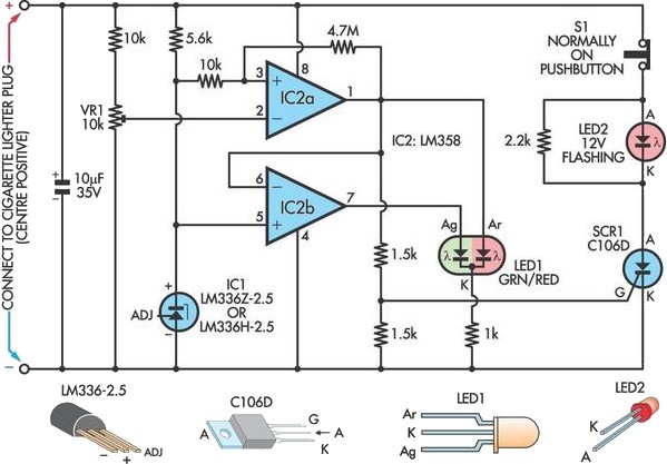
A car battery deteriorates with use, typically lasting no more than four years. Initially, its voltage may drop to just 2V when cranking the engine. As the battery ages, its internal impedance increases, leading to a higher voltage drop...
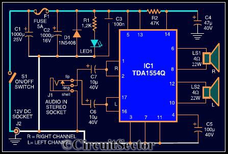
The circuit diagram illustrates a robust stereo amplifier capable of delivering 22W of power. It is based on the widely used single-chip audio power amplifier TDA1554Q (IC1), which is configured as two 22W stereo bridge amplifiers. While listening to...
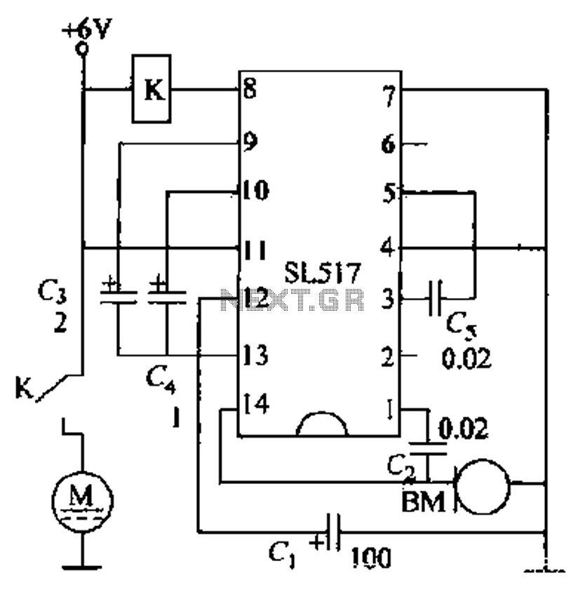
Electric cars utilize a voice circuit principle, where sound signals are captured by a microphone (BM) and processed. The signal is then coupled through a capacitor to an integrated circuit (IC), which includes an internal amplifier that boosts the...

Color TV subcarrier generator. The crystal shown is for 3.58 MHz. The ECG1131 noted on the schematic is a chroma signal amplifier. The ECG1132 is a 16-pin DIP (courtesy of GTE Sylvania Incorporated). The color TV subcarrier generator is an...
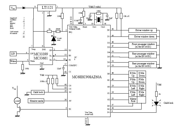
The following circuit illustrates a Car Door Keypad Electronic Circuit Diagram. Features include a lower pin-count and a cost-effective design utilizing the MC68HC908AZ60A microcontroller. The Car Door Keypad Electronic Circuit is designed to enhance vehicle security by providing a user-friendly...
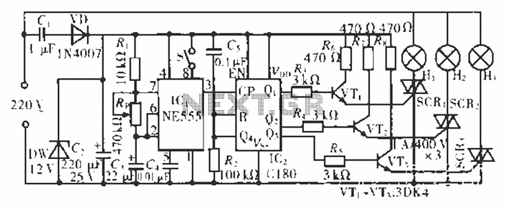
The circuit operates at 220 V AC using a C1 buck converter and a DW regulator. The VD ensures the entire stream is processed, and C2 provides a filtered output of 12 V DC for the voltage supply control...