
9 Second Digital Readout Countdown Timer

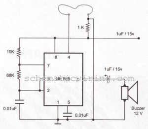
The circuit utilizes a CD4010 up/down counter and a 555 timer to create a visual delay of 9 seconds, which is displayed on a 7-segment LED display. The CD4010 is a dual 4-bit binary counter that can count both up and down, allowing for versatile operation in various applications. In this configuration, the counter is preset to a value of 9 when the switch is activated, which initiates the delay sequence.
When the switch is closed, it triggers the counter to begin counting down from the preset value of 9. The output of the counter can be connected to a 7-segment display driver, which translates the binary output from the CD4010 into a format suitable for visual representation on the LED display. The 555 timer, commonly used for generating precise timing sequences, is disabled during this operation, ensuring that the output remains high and stable while the counter is decrementing.
The 7-segment display will visually indicate the countdown process, providing immediate feedback on the timing status. Upon reaching zero, the circuit can be designed to reactivate the 555 timer or trigger another event, depending on the specific application requirements. This setup is ideal for applications needing a clear and visual indication of time delays, such as in timing circuits, countdown timers, or educational demonstrations of digital counting mechanisms.
Overall, this circuit effectively combines digital counting and visual display technologies to achieve a straightforward yet functional timing solution.This circuit provides a visual 9 second delay using a 7 segment digital readout LED. When the switch is closed, the CD4010 up/down counter is preset to 9 and the 555 timer is disabled with the output held high 🔗 External reference
Related Circuits
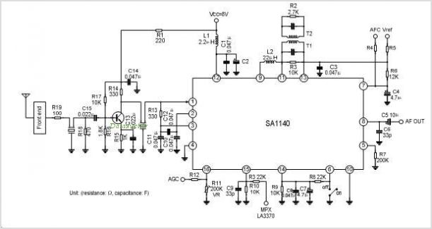
The SA1691 is a monolithic integrated circuit designed for radio cassette tape recorders, clock radios, and headphone radios. This IC includes all functions from the antenna to the audio power amplifier of AM/FM radio, produced by Silan. The SA1691 integrated...
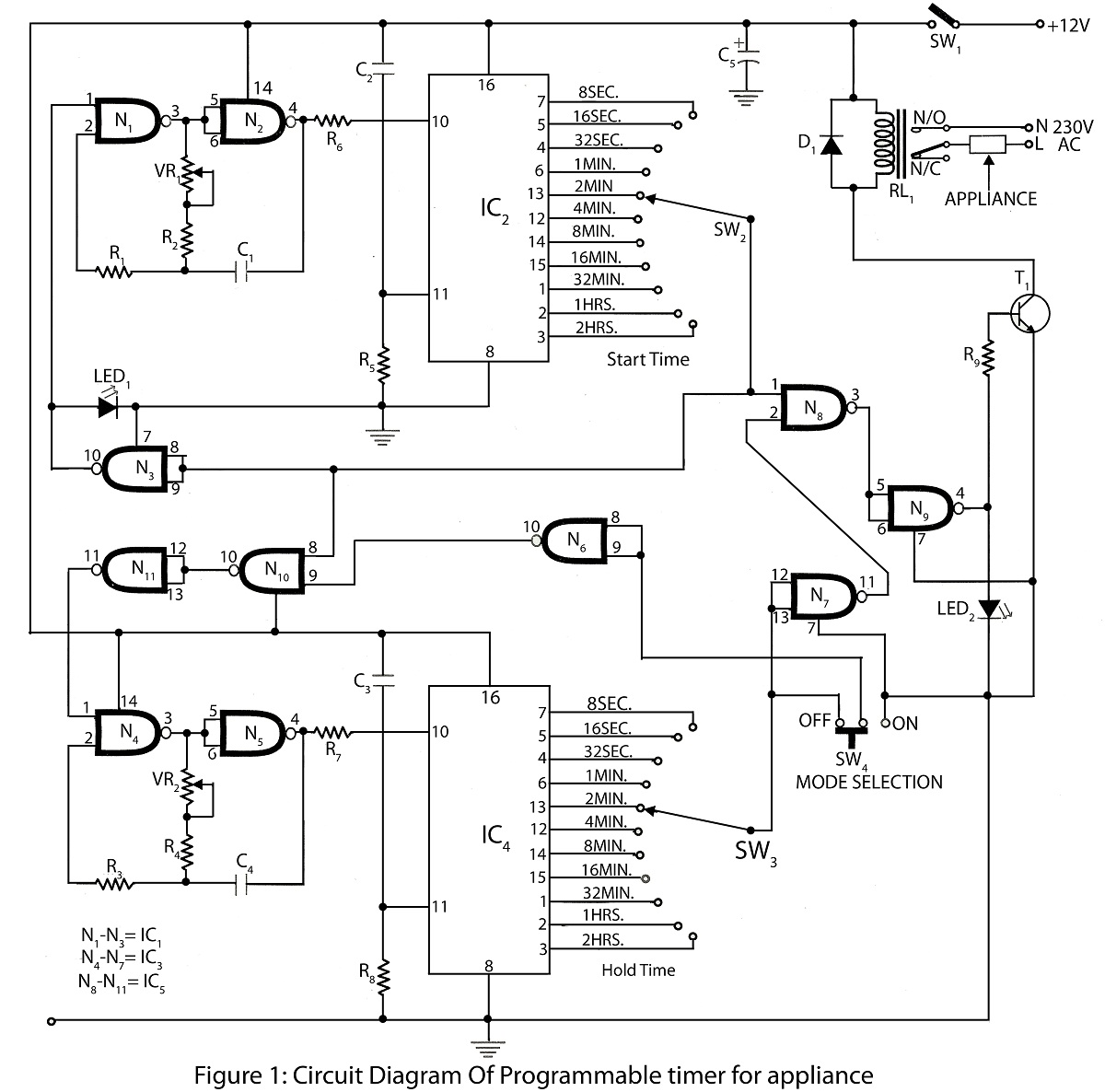
A programmable timer for an appliance circuit is an advanced timer that controls the operation of the appliance. The timer can be set for durations ranging from 8 seconds to 2 hours. A circuit diagram of the programmable timer...
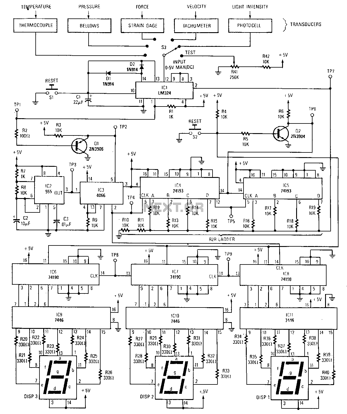
The peak detector tracks and holds the highest output voltage from a transducer by utilizing the charge-storing capability of a capacitor. Initially, the voltage at the inverting input of the comparator is at ground level. When a small voltage...
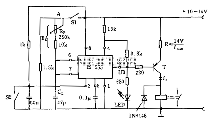
The circuit for the photoelectric switch S1 functions as a control switch for the luggage room light. In its closed operating state, the voltage is positive. If S2 is closed, irrespective of the state of S1, the output terminal...
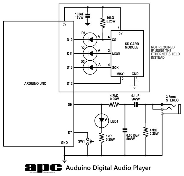
In this series, a diverse exploration of how Arduino interacts with various real-world devices has been presented, from servo motors to ultrasonic range finders, TVs to humidity sensors. The focus now shifts to generating sound using Arduino. The project...
The circuit of a burglar alarm utilizing IC timer 555/556 functions as a security measure to prevent unauthorized entry into a premises. The alarm generates a loud sound when a thin wire connecting resistor R1 with pin 4 of...