
Sega Game Gear Power supply

The power supply circuit for the Sega Game Gear is designed to provide the necessary voltage and current levels required for optimal operation of the gaming device. The circuit typically consists of a regulated power supply that converts an input voltage from a battery or an AC adapter to the specific voltage required by the Game Gear, which is usually around 5V.
Key components of this power supply circuit may include a step-down (buck) converter or a linear voltage regulator, which ensures that the output voltage remains stable despite variations in input voltage or load conditions. Capacitors are often used for filtering to smooth out any voltage ripples and to provide transient response stability. Additionally, diodes may be incorporated to prevent reverse polarity connections, protecting the circuit from potential damage.
The circuit layout should be designed to minimize noise and interference, which is crucial for maintaining the performance of sensitive electronic components within the Game Gear. Proper grounding and trace routing techniques should be employed to ensure reliable operation.
For those interested in a more comprehensive understanding of the circuit design, including component values, schematic diagrams, and practical implementation tips, further information can be accessed on the specified website. This resource will provide insights into various configurations and potential modifications that can enhance the power supply circuit's performance and efficiency.A power supply circuit for sega game gear for the additional collection of your circuit. For a more complete explanation can be found on the website 🔗 External reference
Related Circuits
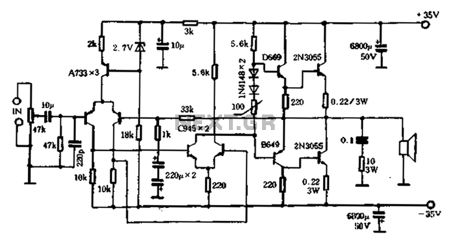
An active high-power tube operates in the MHz range, priced around 3 to 4 yuan, with a transition frequency (fT) exceeding one-fifth of 50 MHz for similar power tubes. This circuit is designed for high reliability in low-frequency high-power...
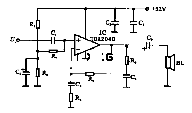
An integrated power amplifier TDA2040 is used in an OTL (Output Transformer-Less) power amplifier circuit, which operates with a +3V single supply as the working voltage. This circuit has a voltage gain of 30 dB (approximately 32 times magnification),...
A truly timeless circuit. LM317 is a versatile and highly efficient 1.2-37V voltage regulator that can provide up to 1.5A of current with a large heat sink. It's ideal for just about any application. Since LM317 is protected against...
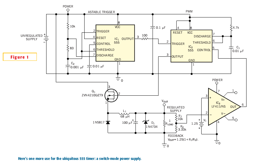
Most switch-mode power supplies utilize a PWM (pulse-width-modulated) output that is regulated through voltage feedback. A 555-timer IC can be used to generate PWM at a low cost. The circuit diagram illustrates how to convert a 555 PWM circuit...
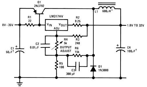
The circuit diagram of this LM317 power supply electronic project requires a few external components. The input voltage for this project must be between 8 and 35 volts, providing a variable output voltage ranging from 1.8 volts to 32...
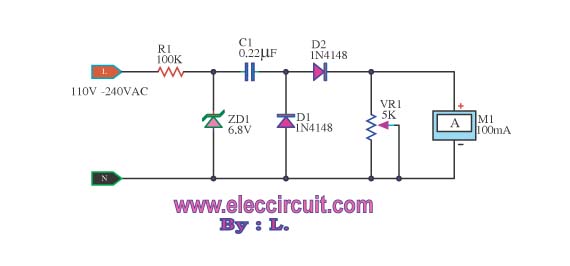
This meter displays the frequency of a power generator, which operates at a voltage range of 110V-240V and a frequency range of 10-100Hz. The output sine waves are converted to square waves. The described frequency meter is designed to accurately...