
Self-powered cw monitor

The circuit described involves a resonant tank circuit typically used in RF (radio frequency) applications. The inductor (L) should be positioned close to the output of the transmitter, allowing the operator to hear the key-down tone, which confirms that the transmitter is active. The inductor is to be securely fastened in place, ensuring stability and consistent performance during operation.
The capacitor (C) is specified as 47 microfarads (µF), which plays a crucial role in filtering and stabilizing the voltage within the circuit, contributing to the overall performance of the RF signal. The resistor (R) has a value of 8 kilohms (kΩ), which is likely used for biasing or limiting current in the circuit, ensuring that the components operate within safe parameters.
The transistor (Q) specified is a HEP 253 or an equivalent component, which functions as a switching element in the circuit, allowing for modulation of the RF signal. The center-tapped transformer (T) with a 500:500 ohm specification is essential for impedance matching between the transmitter and the load, optimizing power transfer and signal clarity.
The inductor (L) is constructed with 2 to 6 turns of wire wound on a 2-inch coil form. The number of turns will affect the inductance value, which is critical for tuning the circuit to the desired frequency, ensuring that the transmitter operates efficiently and effectively. Proper attention must be paid to the winding technique and the physical placement of the coil to minimize losses and maximize performance.
This configuration allows for effective modulation and transmission of RF signals, making it suitable for various applications in amateur radio, communication systems, and other electronic projects where RF transmission is required.Position L near the transmitter output tank to hear the key-down tone. Then tape the coil in place. C = 47 µf, R = 8 K, Q = HEP 253 (or equal), T = 500: 500 ohm center tapped transformer L = 2 to 6 turns on V2" coil form.
Related Circuits

Strictly speaking, this simple circuit should not work. How could anyone expect an ordinary light-dependent resistor (LDR) photocell to detect the change in blood flow as the heart pulsates through a fingertip in natural daylight? The secret lies in...

The PIC16F778A is widely used and is popular among both beginners and professionals due to its FLASH Memory technology, which allows for write/erase operations within thousands of programming cycles. This RISC microcontroller boasts advantages in speed and code compression...
As shown in the figure, D187 is a UART with its RX/TX signals connected through optocouplers N21, N22, and N29, providing complete optoelectronic isolation for the RS-485 communication interface receiver/transmitter D28 and microprocessor D211. D197 serves as a generator,...

This discussion assists in selecting the most appropriate microprocessor supervisor integrated circuit (IC) for specific applications and provides solutions for various common supervisory issues encountered with microprocessors. Microprocessor supervisor ICs are critical components in ensuring the reliable operation of microprocessor-based...

The International Rectifier IRAM109-015SD is a multi-chip hybrid integrated circuit designed specifically for low-power appliance motor control applications, including fans, pumps, and refrigerator compressors. Its compact single in-line package (SIP-S) optimizes PCB space. The device includes several built-in protection...
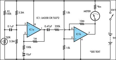
Strictly speaking, this simple circuit should not work. How could anyone expect an ordinary light-dependent resistor (LDR) photo cell to detect changes in blood flow through a fingertip in natural daylight? The secret lies in a high-gain circuit based...