
Lamp touch switch circuit diagram

The circuit design employs a straightforward optocoupler configuration that utilizes neon tubes and photosensitive resistors to achieve a touch-sensitive control mechanism for an AC-powered load. The operation begins with the activation of N1 when a finger makes contact with the metal sheet S1. This contact causes N1 to emit light, which reduces the resistance of RG1, thereby allowing sufficient current to flow through the gate of triac VS1. As VS1 turns on, it energizes the load, represented by bulb H.
The circuit remains in this active state due to the feedback loop created by the illumination of N2, which continues to light up as long as H is on. The light from N2 keeps RG1's resistance low, ensuring that VS1 remains triggered even after the initial contact with S1 is removed. This characteristic allows for sustained operation of the load without requiring continuous contact.
The second part of the circuit involves the interaction with S2. When H is lit and S2 is touched, N3 activates, leading to a decrease in the resistance of RG2. This action triggers triac VS2, which effectively turns off VS1 by interrupting the current flow to the gate. Consequently, the load H is de-energized, completing the control cycle initiated by the user.
The neon tubes used in this circuit operate at a striking voltage of approximately 60V, making them suitable for low-power applications. The load, bulb H, is rated for less than 100W, ensuring that the circuit remains efficient and safe to operate. The copper sheets S1 and S2, sized at 5mm by 5mm, provide adequate surface area for reliable touch detection without requiring complex components or circuitry.
Overall, the simplicity of the circuit design allows for easy assembly and troubleshooting, making it an effective solution for touch-sensitive applications in various electronic projects. The use of readily available components further enhances its accessibility for hobbyists and engineers alike. Circuit principle as shown, neon tubes N1, N2 and photosensitive resistance RG1 constitute an optocoupler. When touching the metal sheet S1 with a finger, N1 light, so RG1 resi stance becomes smaller, so the triac VS1 because sufficient trigger current conduction, so the bulb H energized and lights. At the same time, 220V AC voltage H on the N2 so light, of course, this light shone on RG1, so this time, even touch-up, VS1 remains in the conductive state, namely H remains lit.
FIG neon N3 and photosensitive resistor RG2 constitute another photoelectric coupling device. H lit, if you touch a metal sheet S2, the N3 light, so RG2 resistance becomes smaller, the TRIAC VS2 due to sufficient trigger current conduction, so that its G VS1 pole and T1 extremely short and off, H off. To sum up: touch the S1, H lit; then touch the S2, H off; again and again. N1, N2, N3 with a striking voltage of about 60V neon tube lamp power is less than 100W, S1 and S2 for the copper, the size of 5mm 5mm.
No special requirements other components. The entire circuit structure is simple, as long as the correct assembly and welding, debugging can work properly.
Related Circuits

To create a versatile and generic microcontroller board, the information provided thus far is sufficient. It covers the essential components needed to achieve this. The design of a microcontroller board requires careful consideration of various factors to ensure versatility and...

The circuit utilizes a 555 timer IC to create a lighting group delay effect, as illustrated in Figure 2-46. It consists of the 555 IC along with a resistor and capacitor configuration that establishes the delay. The circuit remains...
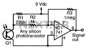
This simple amplifier is compatible with nearly any phototransistor. Although the 741 operational amplifier is designed for use with a split supply, it can also function effectively with a single-sided supply. The described amplifier circuit utilizes the 741 operational amplifier...
The thermocouple cold junction compensation circuit and the MAX6675 converter circuit diagram form a temperature measuring system. The system utilizes a K-type thermocouple connected to the T terminals of the MAX6675, with the cold junction grounded. An 8051 microcontroller...
The VU meter is categorized into two types: those that use needle instruments and those that employ LED columns. A VU meter sound level meter is essential for both tube amplifiers and integrated amplifiers. Currently, there are numerous integrated...
Even including labor, the actual cost of purchasing, stocking, assembly, assembly errors, more expensive PCBs (with additional holes and larger sizes), and the increased difficulty in tuning would likely result in significantly higher expenses. The analysis of costs associated with...