
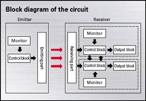
circuit block diagram
The temperature measuring system leverages the MAX6675 thermocouple-to-digital converter, which interfaces seamlessly with the K-type thermocouple to provide accurate temperature readings. The cold junction compensation is essential for ensuring that the temperature readings reflect the actual temperature at the thermocouple's measuring point, rather than being skewed by the ambient temperature at the connection point.
The 8051 microcontroller serves as the central processing unit in this system, managing communication with the MAX6675 and handling data output to the LED display. The P1.1 port's clock signal allows for synchronized data transfer, while the P1.0 port receives the temperature data output from the MAX6675. The low signal on the P1.2 port activates the chip select line, enabling the MAX6675 to respond to the microcontroller's commands.
The system's display utilizes five common cathode LED digital tubes, which are driven by the P0 port through a CCD4511 decoder. This configuration allows for clear visibility of temperature readings, formatted to show one decimal place for precision. The temperature range of 0 to 1024°C is suitable for various applications, including industrial and laboratory settings.
For alarm functionality, the P1.3 port is connected to a sound and light alarm circuit. This feature is crucial for alerting users to potential issues, such as a disconnection of the thermocouple, which could lead to inaccurate readings. The alarm activates a speaker, providing both auditory and visual signals to indicate a fault condition.
The keyboard access through the P2.4 port allows users to interact with the system, potentially enabling features such as calibration, setting temperature thresholds, or switching between different modes of operation. The internal functional units of the circuit are organized in a logical flow, ensuring efficient signal processing and control throughout the system. Each functional block is designed to perform specific tasks, contributing to the overall performance and reliability of the temperature measuring system.thermocouple cold junction compensation and the MAX6675 converter circuit diagram of temperature measuring system composed of The circuit components are used:Temperature measurement system composed by the MAX6675 circuit diagram as shown. K-type thermocouple connected to the MAX6675`s T, T-end of the cold thermocouple grounded. Host selection of 8051, MAX6675 as a slave, from 8051`s P1. 1 serial port to the MAX6675 transmit clock, P1. 0 port to receive the MAX6675 output temperature data. P1. 2 port output low to CS set to 0. System with five common cathode LED digital tube, will be set at ten behind the decimal point, you can measure the temperature of 0 ~ 1024oC, resolution is 0. 1. P0 port is used to drive CCD4511 were then decoding and bit drive 774LS154. P1. 3 port access through the speaker sound and light alarm circuit, open circuit failure occurs when the thermocouple, the speaker alarm.
P2 4 4 keyboard port access. it diagram of the internal functional units, each unit specific circuit diagram of the circuit and so on. [1] "circuit diagram" of the painting has a certain signal flow logic. For example, the signal must come from the launch pad, from the TV antenna input circuit television, after the signal processing circuit television, that high amp circuit, prerelease, color decoding, video, zoom, and color matrix, and other circuits, and finally added to the three CRT electron gun, in coordination with other circuits on the screen in the tube weight was a signal from the TV transmitters.
TV signal flow diagram in the picture, as long as the signal flows through the circuit block diagram of the functional unit, said then the block diagram according to a certain logical order it can be. TV circuit block diagram of the principle of painting in the picture when the TV block diagram of the composition principle, to the functional units are small box on the circuit, but does not involve the internal circuitry of the functional circuit, if a functional unit of the circuit structure is complicated, can draw the block diagram of one or more branches, such as high-frequency tuning circuit can be expressed by a small block diagram, while the IF amplifier is more complex, it needs to be divided into two branches of image and sound.
Also note that the signal flow block diagram of the order must be arranged, for example, high-frequency tuning circuit diagram in the left and then followed in the discharge circuit, the pre-amp circuit, as the color decoding and scanning circuits, video amplifier, a color matrix circuit and tube circuit. IC internal circuit diagram of the painting color TV IF amplifier IC are integrated units, and color decoding and scanning integrated circuit units, and remote control unit of three integrated circuits integrated circuit.
While the internal circuitry of integrated circuits is very complex, but as long as students in practical learning to master the internal circuit diagram is enough to understand how it works. IC internal circuit diagram of the painting should pay attention to three principles: First, the order according to signal to the internal cell circuit, the second is that all functions within the circuit pins are connected with the third, indicating the power pin and ground pin.
The unit circuit of the specific circuit diagram of painting the concrete circuit of the unit circuit of the functional unit is the specific circuit of the circuit, for example, electronic tuner circuit diagram, line scan circuit diagram, 🔗 External reference
Related Circuits
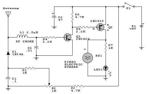
This electronic RF detector project is designed using common transistors and a few standard electronic components. The RF detector responds to RF signals below the standard broadcast band and well over 500 MHz, providing both visual and audible indications...
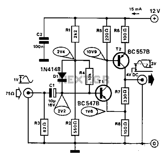
Commonly used for cameras or computers with black and white television connections, the amplifier has a gain of 3 and a bandwidth of 10 MHz. The described circuit is an amplifier designed for applications involving cameras or computers that interface...
An FM transmitter circuit that utilizes a low power configuration, employing an operational amplifier as an audio preamplifier and a single transistor to function as the RF amplifier. This FM transmitter circuit is designed for low power applications, making...
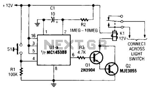
A normally open pushbutton switch (SI) provides a positive input pulse to pin 4 of U1, activating the integrated circuit (IC). The output from U1 at pin 6 delivers base-drive current to a Darlington pair consisting of Q1 and...
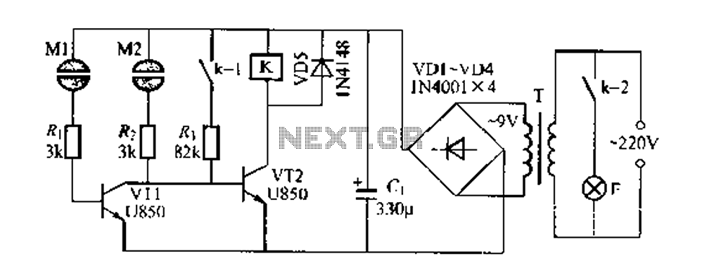
The Darlington circuit is a double-clamp touch switch circuit that features a touch-sensitive sheet and operates with a 20V AC mains supply through an isolated power transformer, ensuring relative safety. Once powered, a 20V optional AC transformer (T) is...
.png)
This document describes a simple engineering project circuit for a mobile cell phone detector (sniffer). This compact mobile communication detector can sense the presence of a mobile device, making it suitable for preventing mobile phone usage in private spaces,...
Warning: include(partials/cookie-banner.php): Failed to open stream: Permission denied in /var/www/html/nextgr/view-circuit.php on line 713
Warning: include(): Failed opening 'partials/cookie-banner.php' for inclusion (include_path='.:/usr/share/php') in /var/www/html/nextgr/view-circuit.php on line 713