
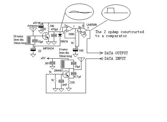
RF communication use a sample circuit(example in AVR)
The analysis of costs associated with electronic assembly encompasses various factors that influence the overall financial implications of a project. When considering the procurement of components, expenses are incurred not only from the purchase price of the parts but also from the logistics of stocking inventory. This includes warehousing costs, which can escalate depending on the volume and variety of components required for assembly.
Assembly processes are prone to errors, which can further inflate costs. Mistakes during assembly can lead to rework or scrapping of components, necessitating additional labor and material expenses. This aspect underscores the importance of employing skilled technicians and implementing quality control measures to mitigate potential errors.
The design of printed circuit boards (PCBs) also plays a critical role in cost determination. More complex PCBs that require additional holes or larger footprints tend to be more expensive to manufacture. This is due to the increased material usage and the intricacies involved in the manufacturing process. Furthermore, such designs may complicate the assembly process, requiring specialized equipment or techniques, which can add to labor costs.
Tuning and testing of assembled circuits represent another layer of expense. More complex designs may require extensive testing procedures to ensure functionality and performance, which can be time-consuming and resource-intensive. As a result, the cumulative effect of these factors can lead to a substantial increase in the overall cost of a project, making careful planning and design optimization essential for cost-effective electronic product development.Even including labor I would think that the real cost of purchasing, stocking, assembly, assembly mistakes, more expensive PCB (more holes, larger), more difficult to tune, etc. would cause it to be much more expensive. 🔗 External reference
Related Circuits
The current loop interface circuit diagram of the AD694 multi-functional sensor signal conditioner is utilized as a digital-to-analog converter (DAC). This current loop interface enables the conversion of digital values into voltage and subsequently into current signals. The circuit...
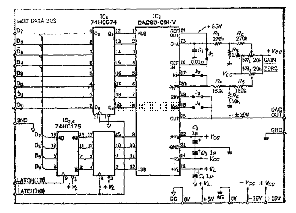
The 8 microcomputer data operates with an 8-bit parallel output, while also accommodating serial input for D-A converters. Typically, data must be entered in two groups and processed as a whole. The requirements for data latching involve 16 straight...
The 8051 microcontroller features a transmit channel and a receive channel for serial communication. The transmit data pin (TXD) is designated as P3.1, while the receive data pin (RXD) is located at P3.0. The serial signals on these pins...
This circuit is useful to show when your line is busy. I used for this a pair of SMT transistors, the LEDs on when the voltage drops down to 40 V. The circuit described functions as an indicator for a...
A brief history: Like many tutorials, this one begins with a historical overview. However, it must be noted that there is limited background information available regarding the development of 7-segment displays. 7-segment displays are widely used electronic components that...
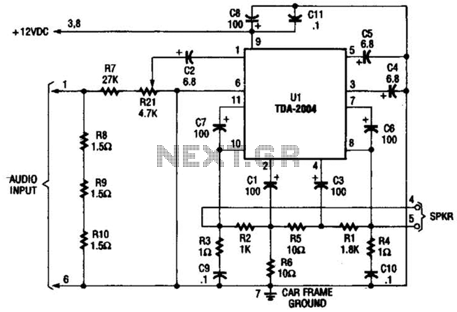
Only one channel of this circuit is shown. The other is practically identical. The input to the circuit, taken from the speaker output of a car radio, is divided into two paths. In one path, a high-power divider network...