
rf detector

The RF detector circuit typically consists of several key components that work together to sense radio frequency signals. At its core, the circuit includes a diode, which acts as a rectifier to convert the RF signal into a usable DC voltage. This voltage can then be analyzed to determine the presence of an RF signal.
A common choice for the diode in such circuits is a Schottky diode due to its fast response time and low forward voltage drop, which enhances the sensitivity of the detector. The output from the diode is often fed into an operational amplifier (op-amp) configured as a comparator. The op-amp compares the rectified voltage to a predefined threshold level. When the voltage exceeds this threshold, indicating the presence of an RF signal, the op-amp output transitions, triggering an alarm or LED indicator.
Additional components may include a variable resistor or potentiometer, which allows for calibration of the sensitivity of the circuit. This adjustment is crucial for optimizing performance across different frequency ranges. Capacitors may also be employed in the circuit to filter out noise and stabilize the power supply, ensuring accurate detection of the RF signals.
The circuit can be powered by a simple battery or a DC power supply, making it portable and easy to integrate into various applications. The design can be further enhanced by incorporating a microcontroller, which can provide more advanced features such as signal processing, data logging, and user interface capabilities.
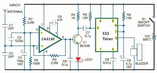
Overall, the RF detector circuit is a straightforward yet effective tool for RF signal detection, suitable for various applications in communications, electronics testing, and amateur radio.Like field strength meter an RF detector circuit is also a useful project to detect a nearby RF signal. The circuit shown here can be used to detect wide band of RF frequencies and provide an alarm when it will detect an RF signal..
🔗 External reference
Related Circuits
This circuit is a motion detection sensor that utilizes a light source and a detector in the form of an infrared motion detector. The motion sensor employs an infrared LED and a phototransistor. The sensitivity of the sensor can...
This electronic schematic allows for the design of a simple cellular phone detector circuit capable of sensing the presence of an activated mobile phone from a distance of 1.5 meters. The capacitor C3 should have lead lengths of 18...
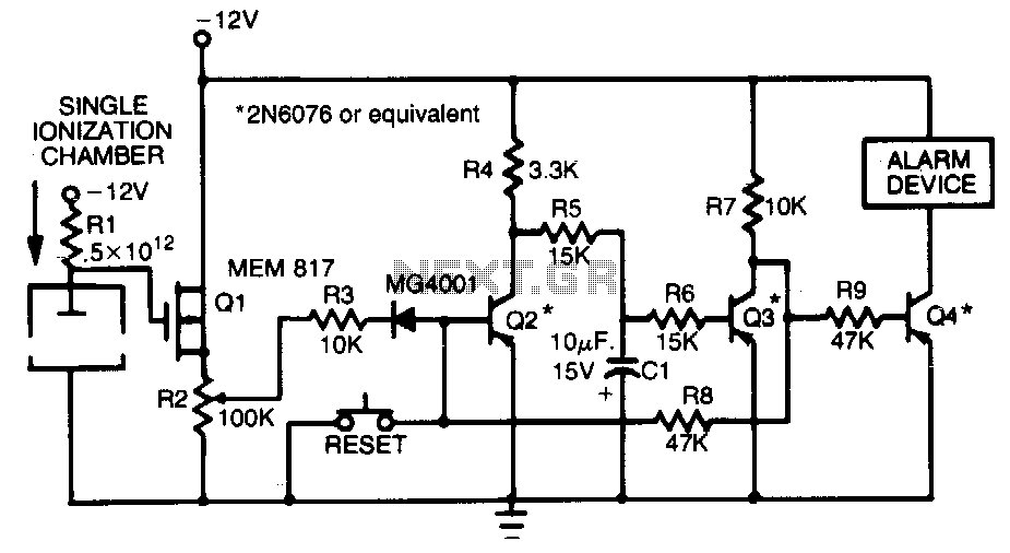
This smoke detector employs a MEM 817 p-channel enhancement mode MOSFET as its buffer amplifier. The sensor operates on the principle that the current decreases when smoke enters the chamber, leading to a negative voltage change at the gate...
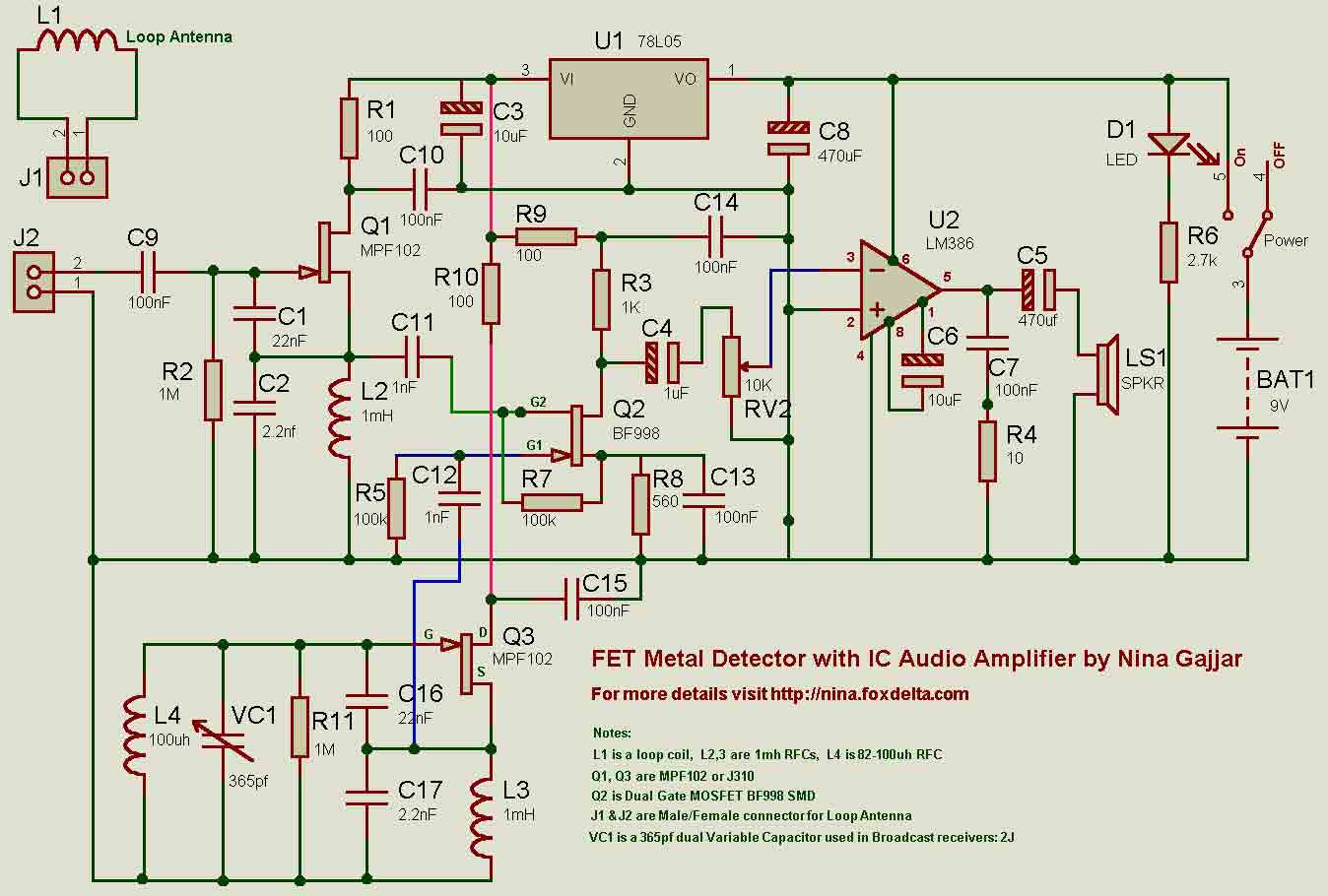
Both oscillators are built using MPF102 or J310 FETs. The Mixer is BF998 dual gate MOSFET. Audio IC amplifier is LM386 which drives a speaker. I have used a stabilized supply for two oscillators and mixer. U1, a 78L05...
The metal detector circuit consists of a probe oscillator, a PLL (phase-locked loop) circuit, and an audio alarm circuit. The probe oscillator includes a detection coil (L), transistor (V1), and several resistors (R1 to R3) and capacitors (C1 to...
In Fig. 1 A precision DC undervoltage relay switch. The op-amp is wired as a voltage comparator, with a reference voltage applied to pin 2 and the test voltage applied to pin 3: the relay turns on when the...