
Using several resistive and capacitive phase shifting trigger circuit
The unidirectional thyristor trigger circuit serves as a fundamental component in controlling AC loads through the TRIAC, which allows for bidirectional current flow. In the configurations shown in Figure 16-28, various methods of triggering the TRIAC are explored, each offering unique advantages depending on the application requirements.
Figures 16-28 (a) and (b) detail direct trigger circuits that utilize simple resistor-capacitor (RC) networks to provide the necessary gate current to the TRIAC. These configurations are straightforward and effective for low-power applications.
In Figure 16-28 (c), a dual diode trigger circuit is presented, which enhances the triggering capability by allowing control over both halves of the AC waveform. This configuration is particularly useful in applications requiring precise phase control.
The arrangement of two light-emitting diodes in inverse parallel, as shown in Figure 16-28 (d), provides a visual indication of the circuit's operation while simultaneously serving as a triggering mechanism. This approach is beneficial in applications where visual feedback is essential.
Figure 16-28 (e) introduces a neon bulb trigger circuit, which is known for its simplicity and reliability in triggering thyristors at a specific voltage threshold. This method is often used in light dimmers and other household appliances.
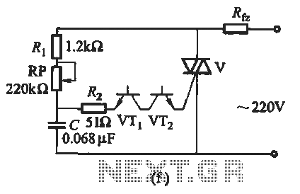
The use of two NPN diodes in Figure 16-28 (f) illustrates a more robust approach to triggering, allowing for higher current handling and improved performance in demanding applications. The selected diodes, such as the 3DG6, are capable of withstanding high reverse voltages.
In Figure 16-28 (g), the anti-parallel diode configuration is explored, which provides a fail-safe mechanism by ensuring that the TRIAC can be triggered regardless of the polarity of the input AC signal.
The triode diac trigger circuit depicted in Figure 16-28 (h) offers a unique triggering mechanism that enhances the precision of the TRIAC's activation point. This is particularly advantageous in applications requiring fine control over power delivery.
Lastly, Figure 16-28 (i) presents a series regulator touch reverse hair circuit, which integrates a touch-sensitive interface to control the TRIAC. This innovative approach allows for user-friendly operation in modern electronic devices.
Overall, the various trigger circuits illustrated in Figure 16-28 provide a comprehensive overview of the different methods available for controlling TRIACs in various applications, highlighting the versatility and adaptability of thyristor technology in modern electronics.The introduction for unidirectional thyristor trigger circuit is equally applicable to the TRIAC. Here are some also for bidirectional circuit shown in Figure 16-28. Figure 16-28 (a) and (b) is a direct trigger circuit; Figure 16-28 (c) for the dual diode to trigger the trigger circuit; Fig. 16-28 (d) for the introduction of two light-emitting diodes in inverse parallel trigger circuit; Figure 16-28 (e) for the introduction of neon bulbs trigger circuit; Figure 16-28 (f) for the introduction of two NPN diode (such as 3DG6, etc.) of the trigger circuit; Figure 16-28 (g) for the introduction of two anti-parallel diode trigger circuit; Figure 16-28 (h) for the introduction of a triode diac trigger circuit; Fig.
16-28 (1) for the introduction of two series regulator touch reverse hair circuit.
Related Circuits
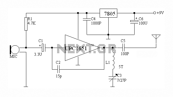
The circuit depicted utilizes the UPC1651 integrated circuit produced by NEC Corporation of Japan. It offers high gain and stability, ensuring optimal performance for microphones. The design incorporates an FM transmitter circuit. The system employs a flexible antenna measuring...
The Colpitts oscillator has been redrawn for clarity. The inductor (L) is approximately 1.5 µH with 19 turns wound on a T50-6 core (yellow). The capacitor (C6) value has been determined experimentally, with a combination of 69 pF (using...
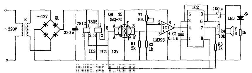
The circuit consists of a buck rectifier and voltage regulator, a gas sensor, a comparator circuit, and an alarm sound circuit. The buck regulator circuit includes a transformer, a bridge rectifier, and components such as QL, IC3 (7812), and...

This design schematic illustrates a Crystal Colpitts oscillator that can be implemented using a transistor and a parallel mode crystal. In this circuit, the crystal functions as an inductance. A large value capacitive divider is utilized between the gate,...

A variable frequency oscillator transistor circuit, primarily functioning as an oscillator, incorporates a crystal resonator and a varactor diode. The output is amplified, typically used for generating high-frequency signals. This 30 MHz transistor circuit features an inductor (LP) connected...
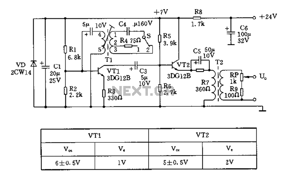
The 450/800Hz oscillation circuit depicted in the figure utilizes transformer coupling. The frequency conversion is achieved by varying the inductance through a variable filter tap (T1). When the switch control signal (S) is set to position 1, the oscillator...